
Kia Seltos SP2 (2021-2026) Service Manual / Body Electrical System / Charging System
Kia Seltos: Body Electrical System / Charging System
Contents:
- On Vehicle Inspection
- Wireless Power Charger (WPC) Description and Operation
- Wireless Power Charger (WPC) Terminal Function
- Wireless Power Charger (WPC) Removal and Installation
- Wireless Charging Indicator Terminal Function
- Wireless Charging Indicator Removal and Installation
- USB Charger Terminal Function
- USB Charger Removal and Installation
On Vehicle Inspection
| On Vehicle Inspection |
| Diagnosis with KDS |
| 1. |
The body electrical system can be more quickly diagnosed for problems with the KDS (Refer to "DTC
guide").
|

Wireless Power Charger (WPC) Description and Operation
| Description |
During IG ON, battery voltage is supplied to the wireless power charger system to transmit an output of 5 W to
mobile phone.
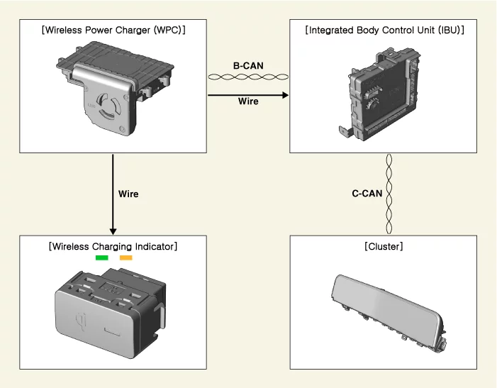
Schematic Diagram
| – |
Wireless power charger (WPC) : Negligence of mobile phone, foreign object detection (FOD) decision.
|
| – |
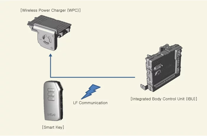
Integrated body control unit (IBU) : Stops charging during the activation of Low Frequency (LF).
|
| – |
Wireless charging indicator : Displays the charging status.
|
| – |
Instrument cluster : Alerts about contact with mobile phone.
|
Wireless Power Charger system Major Functions
| 1. |
Charging Function
|
| 2. |
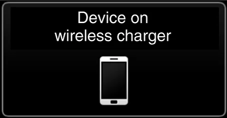
Mobile phone neglect alert function
|
| 3. |
Overheating prevention
|
| 4. |
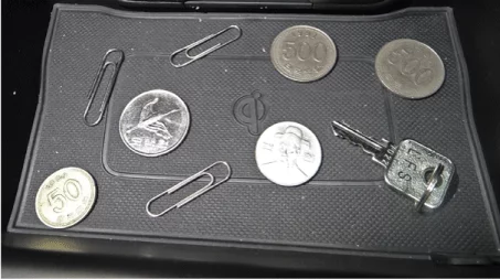
Foreign matter detection
|

| 5. |
IBU unit low frequency (LF) interference prevention
This function prevents interference between the wireless charging frequency and IBU frequency band.
|
| 6. |
Turn the wireless charging function ON/OFF with USM.
|
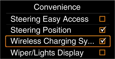
Wireless Power Charger (WPC) System Protection
| Item |
Condition |
State |
| Protects against low/high voltage |
Protects and stops charging under 8.5 V and over 16.5 V |
LED OFF (Stops operation) |
| Charges between 9 - 16 volts |
||
| Protects against reverse voltage |
Protects and stops charging in case of reverse voltage |
LED OFF (Stops operation) |
| Protects against overcurrent |
Protects and stops charging in case of detecting 4 amps |
Amber LED blinks |
| Protects against overheating |
Protects and stops charging in case of detecting 158 °F (70 °C) by internal
temperature sensor of wireless charging module |
Amber LED blinks |
| Resumes under 149 °F (65°C) |
||
| Foreign substances (Coins, clips, precious metals, etc.) |
Protects and stops charging in case of detecting foreign matter (overheating
prevention) |
Amber LED blinks |
| Prevents frequency interference |
Protects and stops charging by activating IBU in case door or tailgate is open |
LED OFF (Stops operation) |
| Resumes in 3.5 seconds after all doors and tailgate are closed and IBU operation is
completed |
||
| Mobile phone neglect alert function |
In case of smart phone on the charging pad when opening the door after IG OFF. |
Displays warning message on the instrument panel (for about 4 - 5 seconds) |
Wireless Power Charger (WPC) Terminal Function
| Connector and Terminal Function |
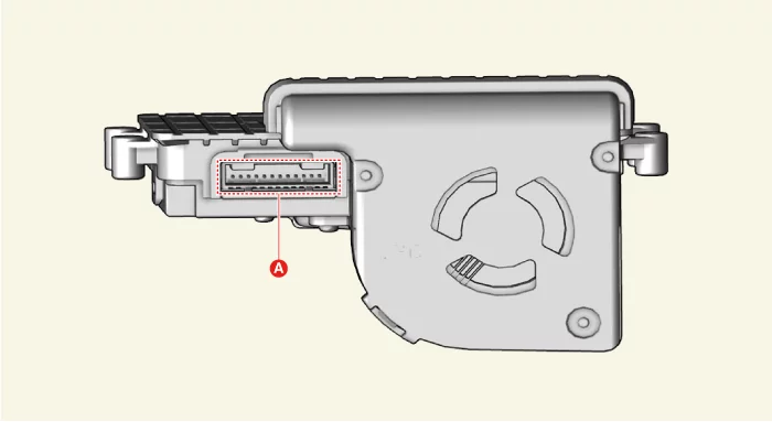
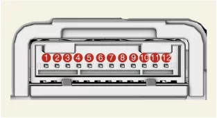
|
Connector A |
Terminal |
Function |
Terminal |
Function |
|
|
1 |
Ground |
7 |
- |
|
2 |
Ground |
8 |
L-CAN (Low) |
|
|
3 |
Wireless charging indicator (Amber) |
9 |
L-CAN (High) |
|
|
4 |
Wireless charging indicator (Green) |
10 |
- |
|
|
5 |
B-CAN (Low) |
11 |
IG 1 |
|
|
6 |
B-CAN (High) |
12 |
Battery ( + ) |
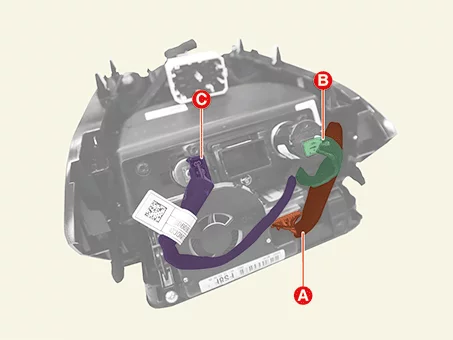
Wireless Power Charger (WPC) Removal and Installation
| Removal |
| 1. |
Remove the console upper cover.
(Refer to Body - "Console Upper Cover")
|
| 2. |
Disconnect the wireless power charger connector (A), USB charger connector (B) and power outlet connector
(C).
|
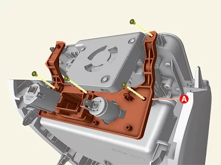
| 3. |
Separate the USB charger bracket (A) after removing the screws.
|
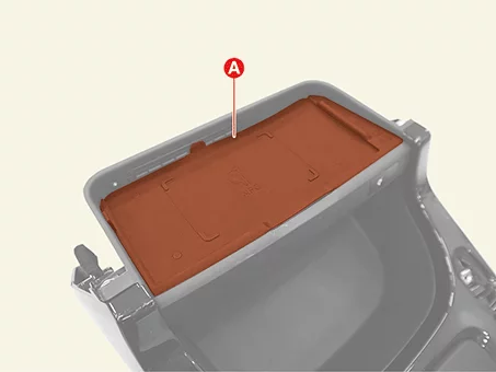
| 4. |
Remove the wireless charging pad (A).
|
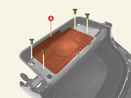
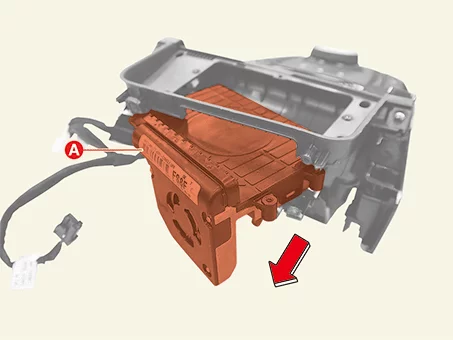
| 5. |
Remove the wireless power charger (A) in the direction of the arrow after removing the screws.
|
| Installation |
| 1. |
Install in reverse order of removal.
|
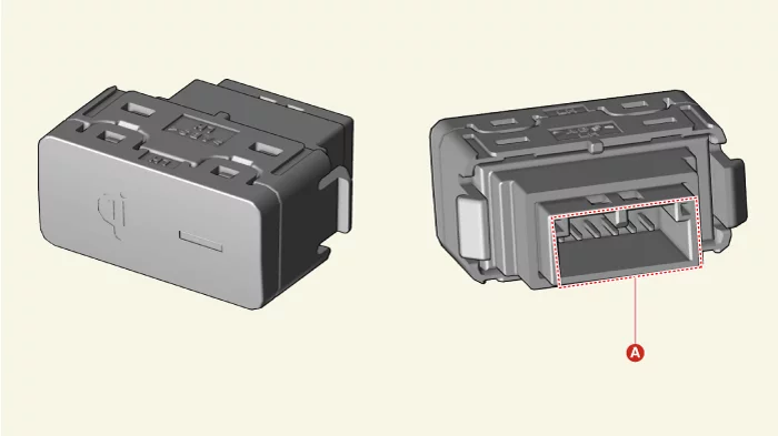
Wireless Charging Indicator Terminal Function
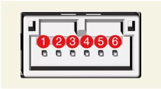
| Connector and Terminal Function |
|
Connector A |
Terminal |
Function |
|
|
1 |
Ground |
|
2 |
Wireless charging indicator (Green) |
|
|
3 |
Wireless charging indicator (Amber) |
|
|
4 |
- |
|
|
5 |
Illumination ( - ) |
|
|
6 |
Illumination ( + ) |
Wireless Charging Indicator Removal and Installation
| Removal |
| 1. |
Remove the console upper cover.
(Refer to Body - "Console Upper Cover")
|
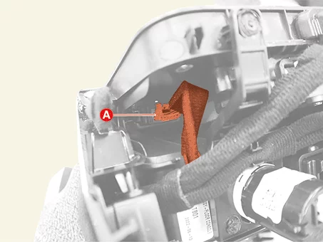
| 2. |
Disconnect the wireless charging indicator connector (A).
|
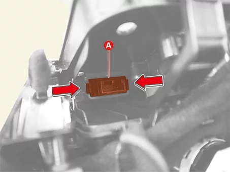
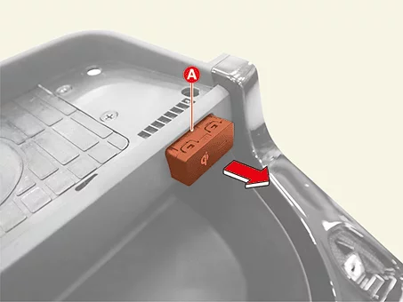
| 3. |
Remove the wireless charging indicator (A) by pressing the hook in the direction of the arrow.
|
| Installation |
| 1. |
Install in reverse order of removal.
|
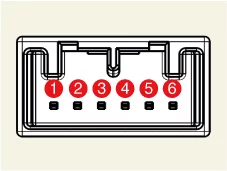
USB Charger Terminal Function
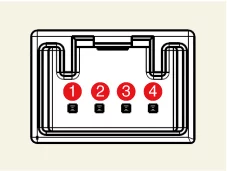
| Connector and Terminal Function |
| [Console Tray] |
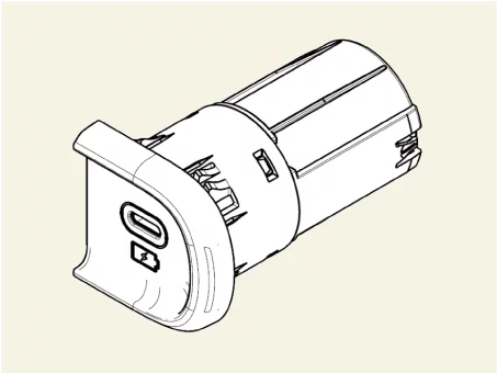
|
Connector |
Terminal |
Function |
|
|
1 |
Ground |
|
2 |
Illumination ( - ) |
|
|
3 |
Illumination ( + ) |
|
|
4 |
ACC |
| [Rear Console Cover] |
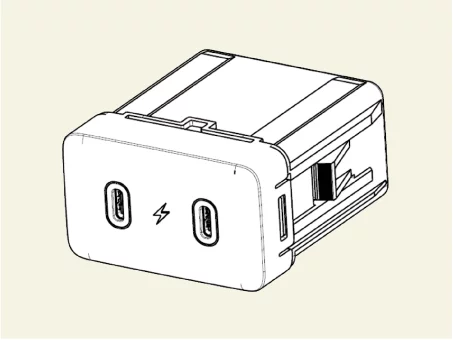
|
Connector |
Terminal |
Function |
|
|
1 |
Ground |
|
2 |
Ground |
|
|
3 |
Illumination ( - ) |
|
|
4 |
Illumination ( + ) |
|
|
5 |
ACC |
|
|
6 |
ACC |
USB Charger Removal and Installation
| Removal |
[Console Tray]
| 1. |
Remove the console upper cover.
(Refer to Body - "Console Upper Cover")
|
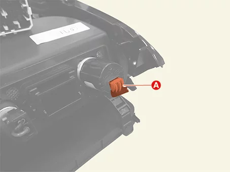
| 2. |
Disconnect the USB charger connector (A).
|
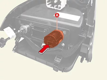
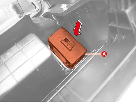
| 3. |
Remove the USB charger (A) by pushing it in the direction of the arrow.
|
[Rear Console Cover]
| 1. |
Remove the floor console assembly.
(Refer to Body - “Floor Console Assembly�)
|
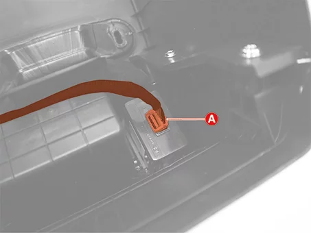
| 2. |
Disconnect the USB charger connector (A).
|
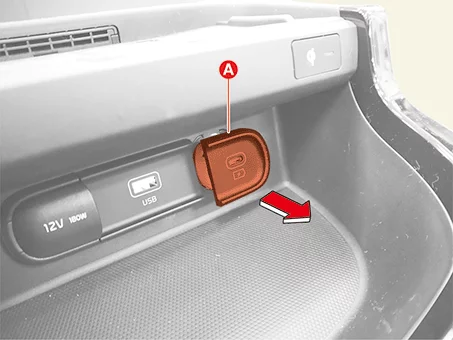
| 3. |
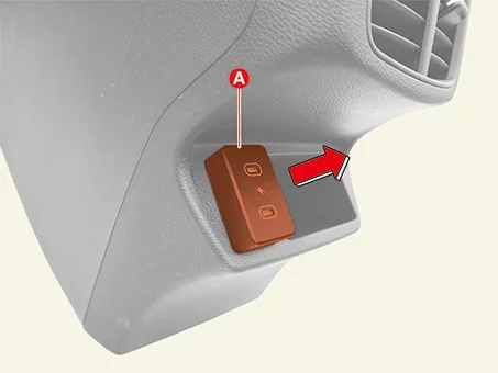
Remove the U SB charger (A) by pushing it in the direction of the arrow.
|
| Installation |
| 1. |
Install in reverse order of removal.
|

