
Kia Seltos SP2 (2021-2026) Service Manual / Engine Electrical System / Charging System
Kia Seltos: Engine Electrical System / Charging System
Contents:
- Description and Operation
- Troubleshooting
- On Vehicle Inspection
- Alternator Specification
- Alternator Components and Components Location
- Alternator Description and Operation
- Alternator On Vehicle Inspection
- Alternator Removal and Installation
- Alternator Disassembly and Reassembly
- Alternator Inspection
- Battery Specification
- Battery Components and Components Location
- Battery Description and Operation
- Battery On Vehicle Inspection
- Battery Removal and Installation
- Battery Cleaning
- Battery Sensor Specification
- Battery Sensor Description and Operation
- Battery Sensor On Vehicle Inspection
- Battery Sensor Removal and Installation
Description and Operation
| Description |
| • |
The alternator consists of a rotor, stator, rectifier, brush, regulator, bearing, and a pulley.
|
| • |
A diode integrated in alternator acts as a rectifier. Rectifier circuit containing diodes converts
alternating current (AC) into direct current (DC) and supply it to the alternator B terminal.
|
| • |
Engine Control Module (ECM) controls the amount of electricity generated by charging control, discharging
control and normal control according to the battery status and the electricity usage of the vehicle.
|
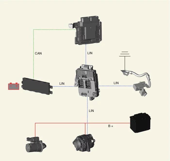
| Alternator Management System (AMS) |
| • |
Alternator Management System (AMS) improves fuel efficiency and manages the battery charging state by
checking vehicle driving conditions, electric load, and battery state.
|
| • |
The Engine Control Module (ECM) controls generating voltage by duty cycle (charging control, discharging
control, normal control) based on the battery conditions and vehicle operating conditions.
|
| • |
The ECM performs discharging control during acceleration to consume battery power and lighten the load on
the alternator. The ECM performs charging control during deceleration to charge the battery.
|
Troubleshooting ➤
On Vehicle Inspection
| On Vehicle Inspection |
| 1. |
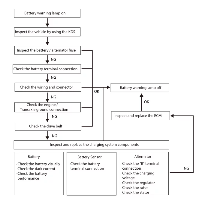
The charging system can be more quickly diagnosed for problems by using the KDS (Refer to "DTC guide").
|
| 2. |
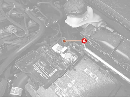
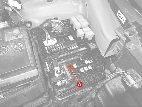
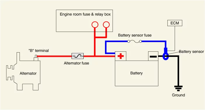
Check the continuity of the fuse.
Alternator fuse (A)
Battery fuse (A)
|
| 3. |
Check the battery terminal for corrosion and connection.
|

| 4. |
Check the connector connection, contact defect, bending, corrosion, deformation or damage.
|
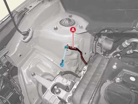
| 5. |
Check the condition of engine ground cable (A) and tight to specified torque.
|
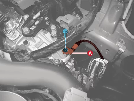
| 6. |
Check the condition of transaxle ground cable (A) and tight to specified torque.
|
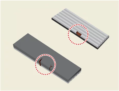
| 7. |
Inspect the drive belt.
|
| 8. |
Check the charging system components
|
Alternator Specification
| Specification |
|
Item |
Specification |
|
Rated output (V, A) |
13.5, 150 |
|
Speed in use (rpm) |
1,000 - 18,000 |
|
Pulley type |
Overrunning Alternator Pulley (OAP) type |
Alternator Components and Components Location
| Component Location |
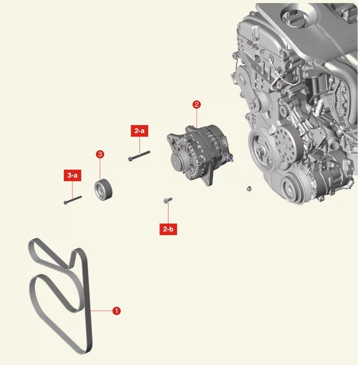
| 1. Drive Belt 2. Alternator 2-a. 29.4 - 41.2 N·m (3.0 - 4.2 kgf·m, 21.7 - 30.4 lb·ft) 2-b. 21.6 - 32.4 N·m (2.2 - 3.3 kgf·m, 15.9 - 23.9 lb·ft) |
3. Pulley 3-a. 39.3 - 49.0 N·m (4.0 - 5.0 kgf·m, 29.0 - 36.1 lb·ft) |
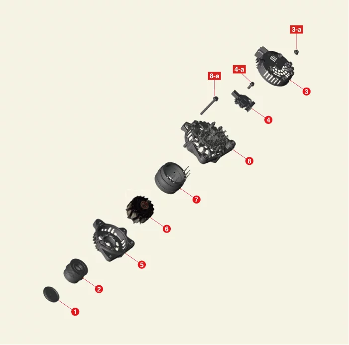
| 1. Cap 2. Pulley 3. Rear Cover 3-a. 3.0 - 4.4 N·m (0.31 - 0.45 kgf·m, 2.2 - 3.3 lb·ft, 26.9 - 39.1 lb·in) 4. Brush & Regulator Assembly 4-a. 3.0 - 4.4 N·m (0.31 - 0.45 kgf·m, 2.2 - 3.3 lb·ft, 26.9 - 39.1 lb·in) |
5. Front Bracket 6. Rotor Assembly 7. Stator 8. Rear Bracket 8-a. 4.5 - 5.5 N·m (0.46 - 0.56 kgf·m, 3.3 - 4.1 lb·ft, 39.9 - 48.6 lb·in) |
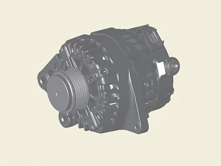
Alternator Description and Operation
| Description |
| • |
The alternator consists of a rotor, stator, rectifier, brush, regulator, bearing, and pulley.
|
| • |
A diode integrated in alternator acts as a rectifier. Rectifier circuit containing diodes converts
alternating current (AC) into direct current (DC) and supply it to the alternator B terminal.
|
| • |
The Engine Control Module (ECM) controls generating voltage by duty cycle (charging control, discharging
control, normal control) based on the battery conditions and vehicle operating conditions.
|
Alternator On Vehicle Inspection ➤
Alternator Removal and Installation
| Removal |
| 1. |
Disconnect the battery negative ( - ) terminal.
|
| 2. |
Remove the drive belt tensioner.
(Refer to Engine Mechanical System - "Drive Belt Tensioner")
|
| 3. |
Disconnect the alternator connector (A).
|
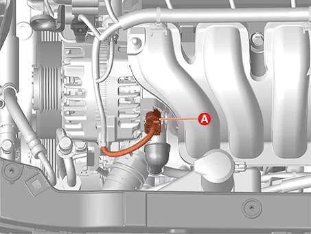
| 4. |
Separate the alternator wiring (A) from the alternator.
|
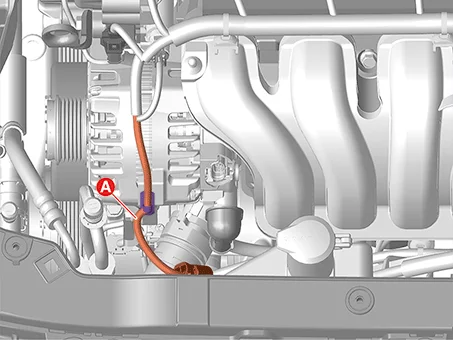
| 5. |
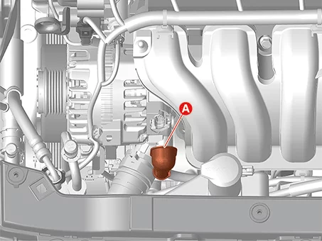
Open the alternator B terminal cover (A).
|
| 6. |
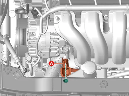
Separate the alternator B terminal cable (A) after removing the nut.
|
| 7. |
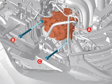
Remove the alternator (A) after removing the bolts.
|
| Installation |
| 1. |
Install in reverse order of removal.
|
Alternator Disassembly and Reassembly
| Special Service Tool |
|
Tool Name / Number |
Illustration |
Description |
|
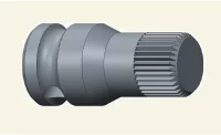
Alternator pulley removal / installation wrench 09373 - 27000 |
|
Used for removing / installing alternator pulley |
| Disassembly |
| 1. |
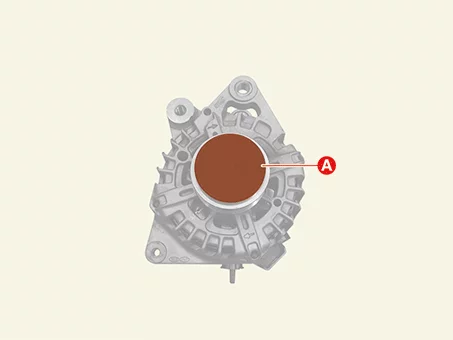
Remove the overrunning alternator pulley cap (A).
|
| 2. |
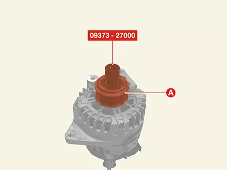
Remove the OAP pulley (A) by using the SST (09373 - 27000).
|
| 3. |
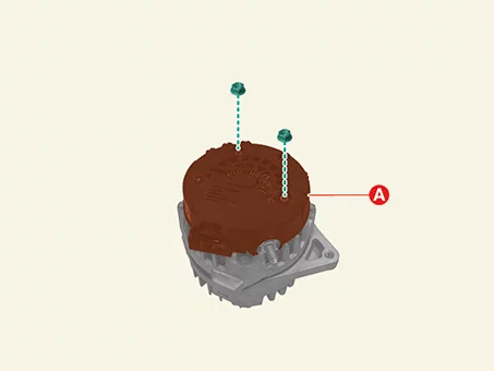
Remove the rear cover (A) after removing the nuts.
|
| 4. |
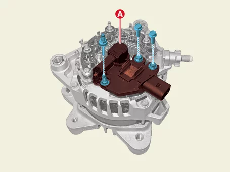
Remove the brush & regulator assembly (A) after removing the bolts and nut.
|
| 5. |
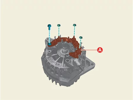
Remove the rectifier assembly (A) after removing the bolt and nuts.
|
| 6. |
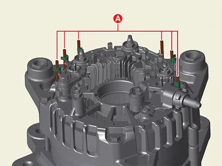
Dissolve the stator lead (A) by using the solder.
|
| 7. |
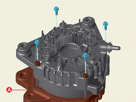
Remove the front bracket (A) after removing the bolts.
|
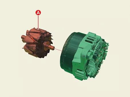
| 8. |
Remove the rotor assembly (A).
|
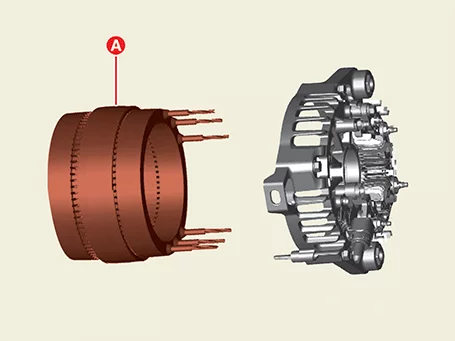
| 9. |
Remove the stator (A) from the rear bracket assembly.
|
| Reassembly |
| 1. |
Reassemble in the reverse order of disassembly.
|
Alternator Inspection
| Inspection |
| [Rotor] |
| 1. |
Check for continuity between each slip ring (A). It is normal if there is continuity.
|
| 2. |
Check that there is continuity between the slip ring and the rotor (B) or rotor shaft (C). It is normal
if there is no continuity.
|
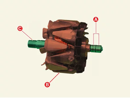
| 3. |
If any of item 1 and 2 above is defective, replace the rotor.
|
| [Stator] |
| 1. |
Check for the continuity between each pair of stator coil (A). It is normal if there is continuity.
|
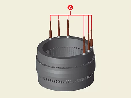
| 2. |
Check for the continuity between the stator coil and the core. It is normal if there is no continuity.
|
| 3. |
If any one of items 1 and 2 above is defective, replace the stator.
|
Battery Specification
| Specification |
|
Item |
Specification |
|
Type |
AGM70L-DIN |
|
Capacity [20HR/5HR] (AH) |
70 / 56 |
|
Cold cranking amperage (A) |
760 (SAE / EN) |
|
Reserve capacity (Min) |
120 |
|
Specific gravity |
1.28 - 1.34 [25°C (77°F)] |
|
Voltage (V) |
12 |
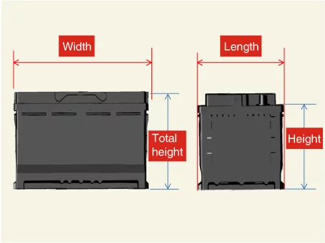
Battery Size
|

Battery Components and Components Location
| Component |
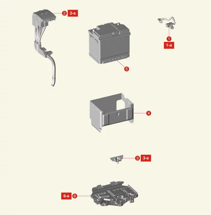
| 1. Battery Negative ( - ) Terminal 1-a. 7.8 - 9.8 N·m (0.8 - 1.0 kgf·m, 5.8 - 7.2 lb·ft) 2. Battery Positive ( + ) Terminal 2-a. 7.8 - 9.8 N·m (0.8 - 1.0 kgf·m, 5.8 - 7.2 lb·ft) 3. Clamp 3-a. 8.8 - 13.7 N·m (0.9 - 1.4 kgf·m, 6.5 - 10.1 lb·ft) |
4. Insulation Pad 5. Battery 6. Battery Tray 6-a. 8.8 - 13.7 N·m (0.9 - 1.4 kgf·m, 6.5 - 10.1 lb·ft) |
Battery Description and Operation
| Description |
The Absorbent Glass Material (AGM) battery controls the electrolyte by absorbing the electrolyte into the
absorbent glass fiber separator inside the battery, and the valve installed on the top of the battery minimizes gas
release.
| Battery Label Information |
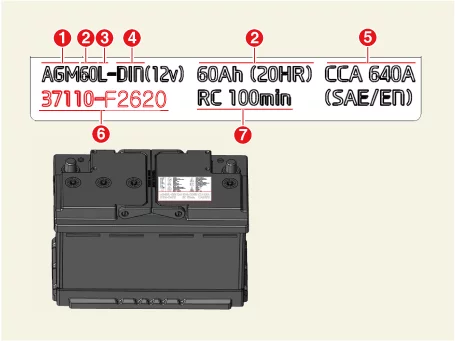
| 1. |
Battery specifications
|
| 2. |
Battery capacity (20 Ah)
|
| 3. |
Terminal location
|
| 4. |
Battery type
|
| 5. |
Cold Cranking Ampere (CCA)
|
| 6. |
Part number
|
| 7. |
Reserve Capacity (RC)
|
Battery On Vehicle Inspection ➤
Battery Removal and Installation
| Removal |
Carefully inspect the battery case for cracks or leakage of electrolytes, and wear thick rubber gloves to
prevent the electrolyte from contacting the skin when disconnecting the battery.
|

| Battery |
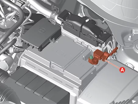
| 1. |
Disconnect the battery negative ( - ) terminal (A).
|
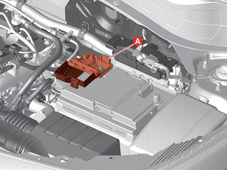
| 2. |
Open the cover and disconnect the battery positive ( + ) terminal after removing the nut.
|
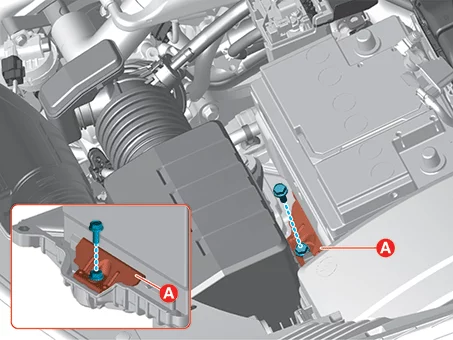
| 3. |
Remove the clamp (A) after removing the bolt.
|
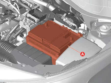
| 4. |
Remove the battery (A).
|
| Battery Tray |
| 1. |
Remove the air cleaner assembly.
(Refer to Engine Mechanical System - "Air Cleaner")
|
| 2. |
Remove the Engine Control Module (ECM).
(Refer to Engine Control / Fuel System - "Engine Control Module
(ECM)")
|
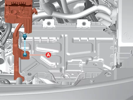
| 3. |
Remove the wiring protector (A) after removing the bolt.
|
| 4. |
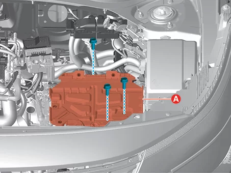
Remove the battery tray (A) after removing bolts.
|
| Installation |
| 1. |
Install in reverse order of removal.
|
Battery Cleaning
| Cleaning |
| 1. |
Remove the battery.
(Refer to Battery - "Removal and Installation")
|
| 2. |
If the battery tray area is damaged due to an electrolyte leak, dissolve baking soda in warm water to
clean the damaged area. Rub the damaged area with a stiff brush or the like, then wipe with a cloth
moistened with an aqueous solution of baking soda.
|
| 3. |
Wash the upper part of the battery with an aqueous solution of baking soda.
|
| 4. |
Check the battery case and cover for the cracks, and replace the battery if any cracks are found.
|
| 5. |
Clean the battery post with a suitable tool.
|
| 6. |
Clean the inside of the battery terminal clamp with a suitable tool and replace any damaged cables or
damaged terminal clamps.
|
| 7. |
Install the battery in the reverse order of removal.
|
Battery Sensor Specification
| Specification |
|
Item |
Specification |
|
Rated voltage (V) |
12 - 14 |
|
Operating voltage (V) |
6 - 18 |
|
Operating temperature [°C (°F)] |
-40 to 105 (-40 to 221) |
|
Parasitic Current (uA) |
Maximum 300 |
Battery Sensor Description and Operation
| Description |
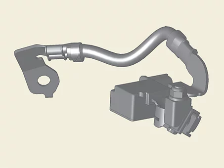
Battery sensor is mounted on the battery negative ( - ) terminal. It transmits battery voltage, current,
temperature information to Engine Control Module (ECM). ECM controls generating voltage by duty cycle based on these
signals.
Battery Sensor On Vehicle Inspection
| On Vehicle Inspection |
| 1. |
Inspect the parasitic current.
(Refer to Charging System - "Battery")
|
| 2. |
If the parasitic current is normal, replace the battery sensor and perform the following procedure.
|
Battery Sensor Removal and Installation
| Removal |
| 1. |
Remove the Engine Control Module (ECM).
(Refer to Engine Control / Fuel System - "Engine Control Module
(ECM)")
|
| 2. |
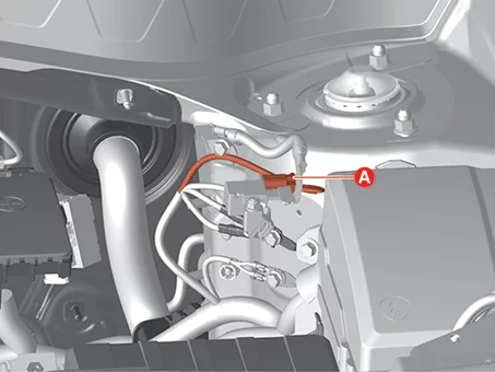
Disconnect the battery sensor connector (A).
|
| 3. |
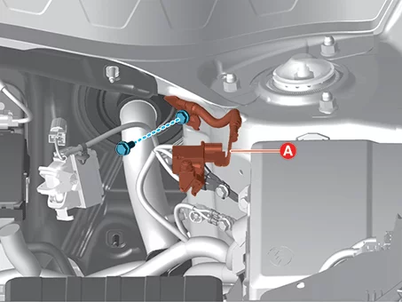
Remove the battery sensor (A) after removing the bolt.
|
| Installation |
| 1. |
Install in reverse order of removal.
|


Other information:
Kia Seltos SP2 (2021-2026) Service Manual: Tire Pressure Monitoring System (TPMS)
The Tire Pressure Monitoring System (TPMS) in the Kia Seltos detects tire pressure and displays tire pressure information on the LCD display. Low tire pressure telltale / TPMS malfunction indicator Low tire pressure position telltale shown on the LCD display Tire Pressure Indicator You can check tire pressure in the Information () mode on the cluster.