Contents:
Accelerator Position Sensor (APS) Specification
Accelerator Pedal Position
|
Output voltage (V)
|
APS1
|
APS2
|
Accelerator pedal is not pressed (*E.C.P)
|
0.7 - 0.8
|
0.325 - 0.425
|
Accelerator pedal is fully pressed (*W.O.T)
|
3.98 - 4.22
|
1.93 - 2.17
|
*E.C.P : Electrically Close Position
*W.O.T : Wide Open Throttle
Accelerator Position Sensor (APS) Description and Operation
|
•
|
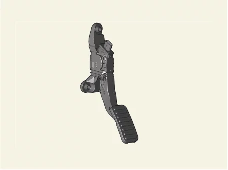
Accelerator Position Sensor (APS) is mounted on the accelerator pedal module and is an important sensor
that transmits the driver's accelerating action to Engine Control Module (ECM) to determine the amount of
fuel injection according to the required acceleration speed.
|
|
•
|
The APS is one of the most important sensors in engine control system, which consists of the two sensors
working individually.
|
|
•
|
Each sensor is composed of an independent circuit, Sensor 2 outputs 50% of signal value of Sensor 1 and
the APS is determined to be a fault when the proportion of voltage for each sensor is out of certain range.
|
Accelerator Position Sensor (APS) On Vehicle Inspection
| 1. |
The engine control system can be more quickly diagnosed for problems by using the KDS (Refer to "DTC
guide").
| (1)
|
Self diagnosis : Inspect the Diagnostic Trouble Code (DTC) using the KDS
(Refer to DTC guide when fault code is found)
|
| (2)
|
Data analysis : Checking the system input/output data state
(Data Analysis → System Selection → Engine)
Accelerator Pedal Position
|
Output voltage (V)
|
APS1
|
APS2
|
Accelerator pedal is not pressed (*E.C.P)
|
0.7 - 0.8
|
0.325 - 0.425
|
Accelerator pedal is fully pressed (*W.O.T)
|
3.98 - 4.22
|
1.93 - 2.17
|
*E.C.P : Electrically Close Position
*W.O.T : Wide Open Throttle
|
|
Refer to the KDS screen for operating conditions and details
|
|
Accelerator Position Sensor (APS) Removal and Installation
| 1. |
Disconnect the battery negative ( - ) terminal.
|
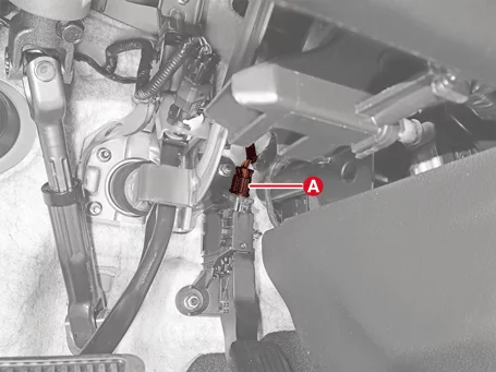
| 2. |
Disconnect the accelerator pedal module connector (A).
|
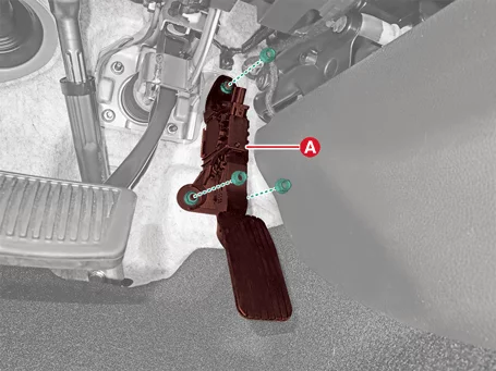
| 3. |
Remove the accelerator pedal module (A) after removing the nuts.
Tightening torque :
12.7 - 15.7 N·m (1.3 - 1.6 kgf·m, 9.4 - 11.6 lb·ft)
|
|
| 1. |
Install in reverse order of removal.
|
•
|
Install the accelerator pedal module to the specified torque.
|
|
•
|
If the accelerator pedal module is dropped, it may cause internal damage. (Do not reuse)
|
|
|
Camshaft Position Sensor (CMPS) Specification
Item
|
Specification
|
Operating voltage (V)
|
4.75 - 5.25
|
Current consumption (mA)
|
Maximum 10
|
Camshaft Position Sensor (CMPS) Components and Components Location
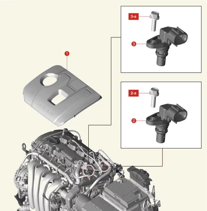
1. Engine Cover
2. Camshaft Position Sensor (CMPS)
- Exhaust
2-a. 9.8 - 11.8 N·m (1.0 - 1.2 kgf·m, 7.2 - 8.7 lb·ft)
|
3. Camshaft Position Sensor (CMPS) - Intake
3-a.
9.8 - 11.8 N·m (1.0 - 1.2 kgf·m, 7.2 - 8.7 lb·ft)
|
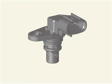
Camshaft Position Sensor (CMPS) Description and Operation
|
•
|
The Camshaft Position Sensor (CMPS) is a hall sensor, which detects the camshaft position by using a hall
element.
|
|
•
|
It is synchronized with Crankshaft Position Sensor (CKPS) and detects the piston position of each
cylinder which cannot be detected by the CKPS.
|
|
•
|
The two CMPS are installed on engine head cover of bank 1 and 2 (intake, exhaust) respectively and use a
target wheel installed on the camshaft.
|
|
•
|
Engine Control Module (ECM) detects the cycle of each cylinder based on the CMPS signal and controls the
fuel injection of each cylinder.
|
Camshaft Position Sensor (CMPS) On Vehicle Inspection
| 1. |
The engine control system can be more quickly diagnosed for problems by using the KDS (Refer to "DTC
guide").
| (1)
|
Self diagnosis : Inspect the Diagnostic Trouble Code (DTC) using the KDS
(Refer to DTC guide when fault code is found)
|
| (2)
|
Actuation test : Checking the Camshaft Position Sensor (CMPS) operation condition
(Data Analysis → System Selection → Engine → Actuation test → Oil Control Valve - Intake Bank1 /
Oil Control Valve - Exhaust Bank1 (Option))
|
|
Refer to the KDS screen for operating conditions and details
|
|
| 1. |
Check signal waveform of Camshaft Position Sensor (CMPS) by using a KDS.
Specified value : Refer to "DTC diagnostic guide"
|
|
Camshaft Position Sensor (CMPS) Removal and Installation
|
Wait until cooling the engine to prevent scalding by engine overheating.
|
Intake
| 1. |
Disconnect the battery negative ( - ) terminal.
|
| 2. |
Remove the engine cover.
(Refer to Engine Mechanical System - "Engine Cover")
|
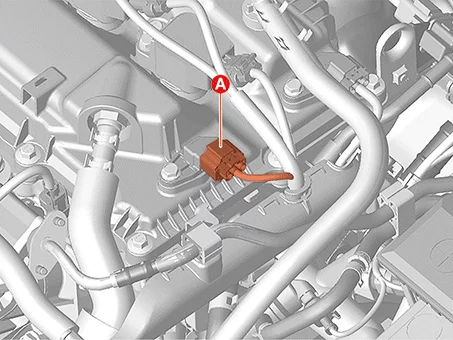
| 3. |
Disconnect the Camshaft Position Sensor (CMPS) connector (A).
|
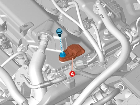
| 4. |
Remove the CMPS (A) after removing the bolt.
Tightening torque :
9.8 - 11.8 N·m (1.0 - 1.2 kgf·m, 7.2 - 8.7 lb·ft)
|
|
Exhaust
| 1. |
Disconnect the battery negative ( - ) terminal.
|
| 2. |
Remove the engine cover.
(Refer to Engine Mechanical System - "Engine Cover")
|
| 3. |
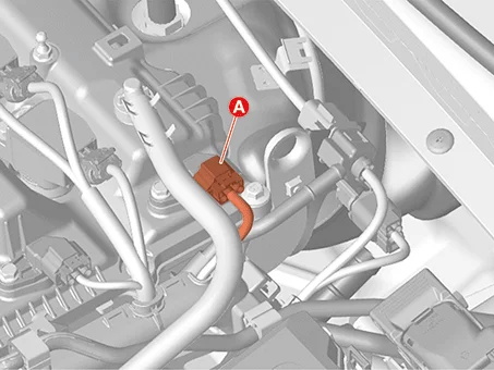
Disconnect the Camshaft Position Sensor (CMPS) connector (A).
|
| 4. |
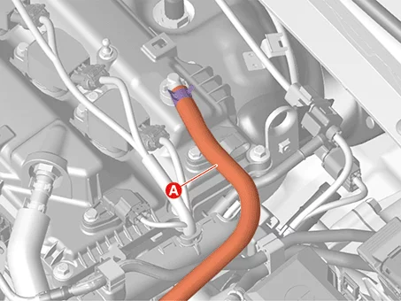
Remove the breather hose (A).
|
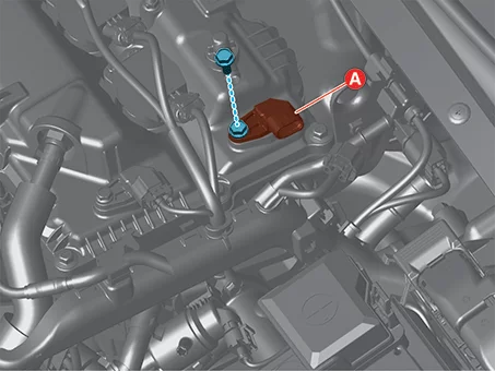
| 5. |
Remove the CMPS (A) after removing the bolt.
Tightening torque :
9.8 - 11.8 N·m (1.0 - 1.2 kgf·m, 7.2 - 8.7 lb·ft)
|
|
| 1. |
Install in reverse order of removal.
|
•
|
Install the Camshaft Position Sensor (CMPS) to the specified torque.
|
|
•
|
If the CMPS is dropped, it may cause internal damage. (Do not reuse)
|
|
•
|
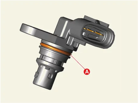
Apply the engine oil to the O-ring (A).
|
|
•
|
Install the CMPS by pushing it into the installation hole firmly. and be careful not to
damage the sensor.
|
|
|
Crankshaft Position Sensor (CKPS) Specification
Item
|
Specification
|
Operating voltage (V)
|
4.5 - 5.5
|
Current consumption (mA)
|
6.8
|
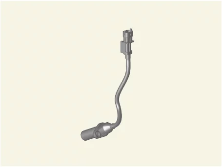
Crankshaft Position Sensor (CKPS) Components and Components Location
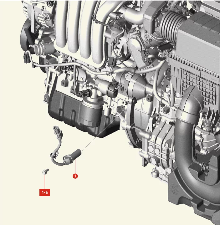
1. Crankshaft Position Sensor (CKPS)
1-a. 9.8 -
11.8 N·m (1.0 - 1.2 kgf·m, 7.2 - 8.7 lb·ft)
|
Crankshaft Position Sensor (CKPS) Description and Operation
|
•
|
The Crankshaft Position Sensor (CKPS) is a sensor that detects the engine rotation speed (rpm).
|
|
•
|
The engine rotation speed (rpm) is the most important variable in the electronic control engine, and if
the engine rotation speed signal is not input to the Engine Control Module (ECM), the engine may stop due to
the CKPS signal not being input.
|
|
•
|
The CKPS determines which stroke the current piston position is on by the target-wheel, and the
target-wheel consists of 58 slots and 2 empty slots at 360 degrees of crank angle (CA).
|
Crankshaft Position Sensor (CKPS) On Vehicle Inspection
| 1. |
The engine control system can be more quickly diagnosed for problems by using the KDS (Refer to "DTC
guide").
| (1)
|
Self diagnosis : Inspect the Diagnostic Trouble Code (DTC) using the KDS
(Refer to DTC guide when fault code is found)
|
Refer to the KDS screen for operating conditions and details
|
|
|
| 1. |
Check signal waveform of Crankshaft Position Sensor (CKPS) by using a KDS.
Specified value : Refer to "DTC diagnostic guide"
|
|
Crankshaft Position Sensor (CKPS) Removal and Installation
| 1. |
Disconnect the battery negative ( - ) terminal.
|
| 2. |
Remove the engine compartment under cover.
(Refer to Engine Mechanical System - "Engine Room Under Cover")
|
| 3. |
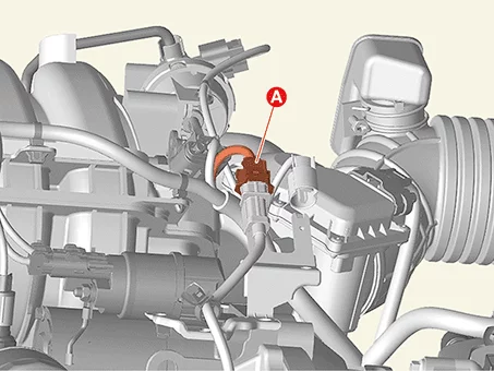
Disconnect the Crankshaft Position Sensor (CKPS) connector (A).
|
| 4. |
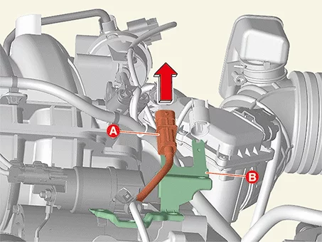
Remove the connector (A) from the bracket (B) by pushing it in the direction of the arrow.
|
| 5. |
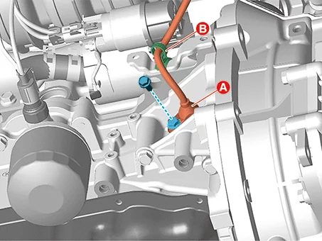
Remove the CKPS (A) and the wiring clip (B) after removing the bolt.
Tightening torque :
9.8 - 11.8 N·m (1.0 - 1.2 kgf·m, 7.2 - 8.7 lb·ft)
|
|
| 1. |
Install in reverse order of removal.
|
•
|
Install the Crankshaft Position Sensor (CKPS) to the specified torque.
|
|
•
|
If the CKPS is dropped, it may cause internal damage. (Do not reuse)
|
|
•
|
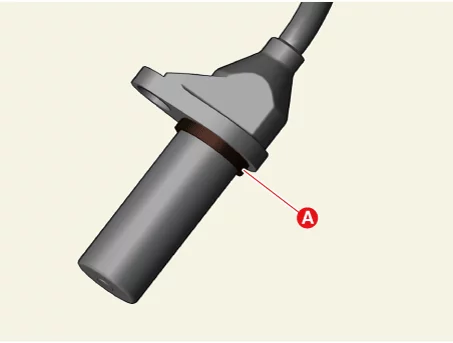
Apply the engine oil to the O-ring (A).
|
|
|
CVVT Oil Control Valve (OCV) Specification
Item
|
Specification
|
Coil resistance (MΩ)
|
Minimum 1 [@500 VAC, 20°C (68°F)]
|
CVVT Oil Control Valve (OCV) Components and Components Location
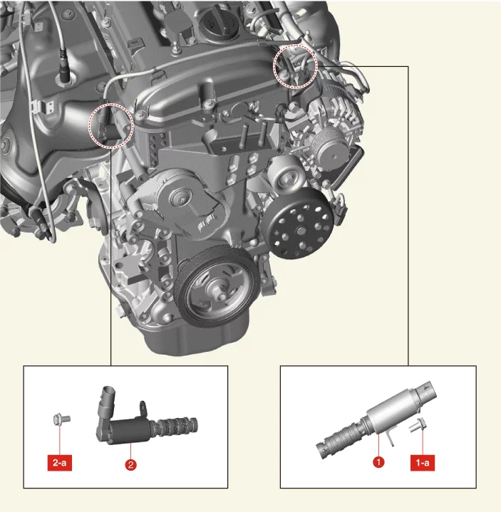
1. Oil Control Valve (OCV) - Intake
1-a.9.8 - 11.8
N·m (1.0 - 1.2 kgf·m, 7.2 - 8.7 lb·ft)
|
2. Oil Control Valve (OCV) - Exhaust
2-a. 9.8 -
11.8 N·m (1.0 - 1.2 kgf·m, 7.2 - 8.7 lb·ft)
|
CVVT Oil Control Valve (OCV) Description and Operation
|
•
|
The Continuous Variable Valve Timing (CVVT) system uses Engine Control Module (ECM) control signals that
vary with engine RPM and load to advance or retard the timing of opening/closing the intake or exhaust
valve.
|
|
•
|
According to the valve overlap and underlap between the intake and exhaust valve by CVVT, there are
effects such as reduce the pumping loss, occur internal (Exhaust Gas Recirculation (EGR) and improve the
combustion stability and volumetric efficiency. For these reasons, fuel efficiency and engine performance
are improved, and the exhaust gas (NOx, HC) decreases.
|
|
•
|
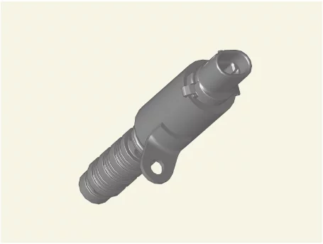
The CVVT Oil Control Valve (OCV) supplies or discharges the oil to a cam phaser by changing the path of
engine oil, receiving the PWM (Pulse Width Modulation) signal of ECM.
|
|
•
|
The oil from the OCV changes the phase of the cam shaft by advancing or retarding the cam shaft by
rotating the rotor connected to the cam shaft inside the cam phaser.
|
CVVT Oil Control Valve (OCV) On Vehicle Inspection
| 1. |
Disconnect the battery negative ( - ) terminal.
|
| 2. |
Remove the engine cover.
(Refer to Engine Mechanical System - "Engine Cover")
|
| 3. |
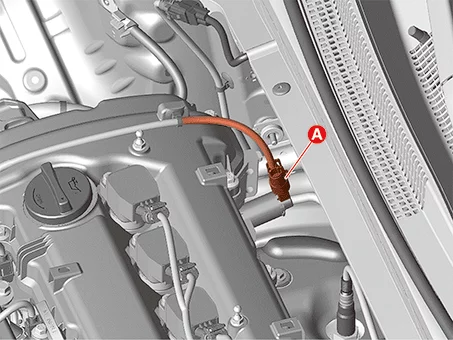
Measure the resistance between terminals after disconnecting the Oil Control Valve (OCV) connector (A).
Intake
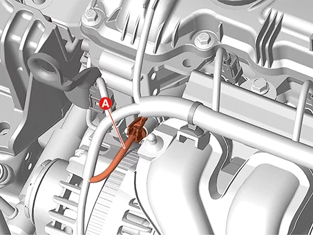
Exhaust
|
| 4. |
Check that the resistance is within the specification.
Item
|
Specification
|
Coil resistance (MΩ)
|
Minimum 1 [@500 VAC, 20°C (68°F)]
|
|
CVVT Oil Control Valve (OCV) Removal and Installation
| 1. |
Disconnect the battery negative ( - ) terminal.
|
| 2. |
Remove the engine cover.
(Refer to Engine Mechanical System - "Engine Cover")
|
| 3. |
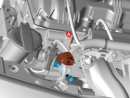
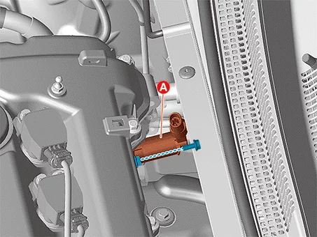
Disconnect the Oil Control Valve (OCV) connector (A).
[Intake]
[Exhaust]
|
| 4. |
Remove the OCV (A) after removing the bolt.
Tightening torque :
9.8 - 11.8 N·m (1.0 - 1.2 kgf·m, 7.2 - 8.7 lb·ft)
|
[Intake]
[Exhaust]
|
| 1. |
Install in reverse order of removal.
|
•
|
Install the Oil Control Valve (OCV) to the specified torque.
|
|
•
|
If the OCV is dropped, it may cause internal damage. (Do not reuse)
|
|
•
|
Apply the engine oil to the O-ring.
|
|
|
Electronic Throttle Control (ETC) Module Specification
Item
|
Specification
|
Motor
|
Type
|
DC Motor
|
Operating voltage (V)
|
7.5 - 16
|
Coil resistance (Ω)
|
0.3 - 100 [20°C (68°F)]
|
Sensor
|
Supply voltage (V)
|
5
|
Sensor output voltage (V)
|
Throttle angle (°)
|
TPS 1
|
TPS 2
|
0
|
0.5
|
4.5
|
10
|
0.96
|
4.05
|
20
|
1.41
|
3.59
|
30
|
1.87
|
3.14
|
40
|
2.32
|
2.68
|
50
|
2.78
|
2.23
|
60
|
3.23
|
1.77
|
70
|
3.69
|
1.32
|
80
|
4.14
|
0.86
|
90
|
4.60
|
0.41
|
98
|
4.65
|
0.35
|
*E.C.P (0°)
|
0.5
|
4.5
|
*W.O.T (86°)
|
4.41
|
0.59
|
*E.C.P : Electrically Close Position
*W.O.T : Wide Open Throttle
Electronic Throttle Control (ETC) Module Components and Components Location
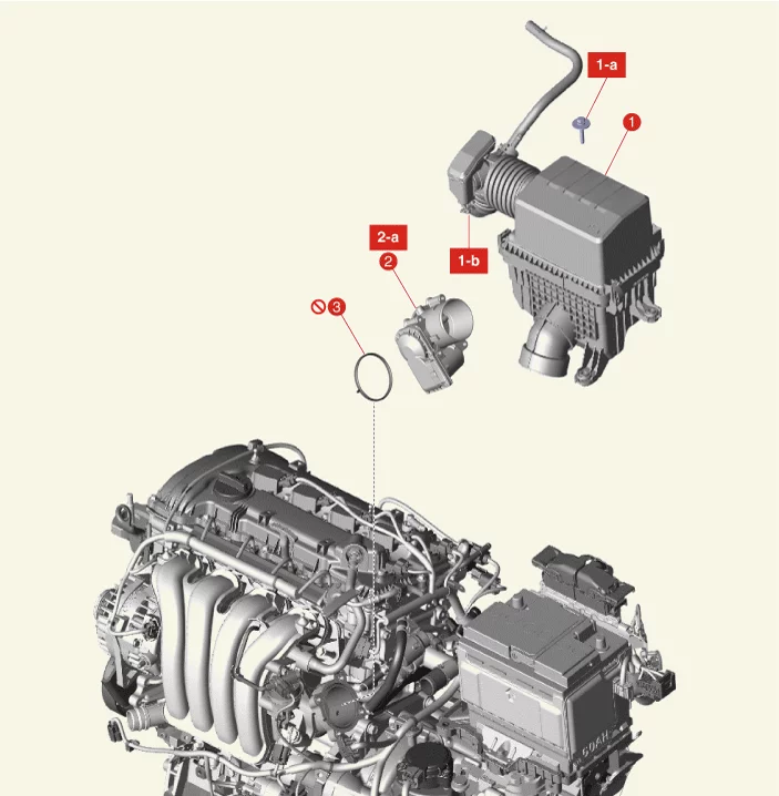
1. Air Cleaner
1-a. 3.9 - 5.9 N·m (0.4 - 0.6 kgf·m,
2.9 - 4.3 lb·ft, 34.7 - 52.1 lb·in)
1-b. 2.9 - 4.9 N·m (0.3 - 0.5 kgf·m, 2.2 - 3.6 lb·ft, 26.0 - 43.4
lb·in)
|
2. Electronic Throttle Control (ETC) Module
2-a.
9.8 - 11.8 N·m (1 - 1.2 kgf·m, 7.2 - 8.7 lb·ft)
3. ETC Module Gasket
|
Electronic Throttle Control (ETC) Module Description and Operation
|
•
|
Electronic Throttle Control (ETC) system is a system that controls the throttle valve electronically.
|
|
•
|
The ETC module consists of a throttle body with an integrated control motor and Throttle Position Sensor
(TPS).
|
|
•
|
The Engine Control Module (ECM) uses the Accelerator Position Sensor (APS) signal to calculate the target
throttle angle; the position of the throttle is then adjusted by ECM control via the ETC motor.
|
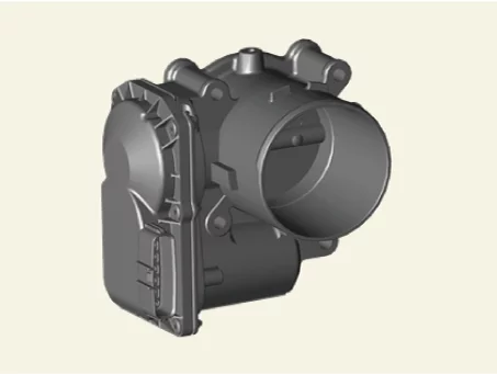
Electronic Throttle Control (ETC) Module Troubleshooting
Item
|
Fail Safe
|
Electronic Throttle Control (ETC) motor
|
Throttle valve stuck at 9.2°
|
Throttle Position Sensor (TPS)
|
TPS 1 fault
|
Using the TPS 2 signal
|
TPS 2 fault
|
Using the TPS 1 signal
|
TPS 1, 2 fault
|
Throttle valve stuck at 9.2°
|
Accelerator Position Sensor (APS)
|
APS 1 fault
|
Using the APS 2 signal
|
APS 2 fault
|
Using the APS 1 signal
|
APS 1, 2 fault
|
Throttle valve stuck at 9.2°
|
|
When throttle value is stuck at 9.2°, engine speed is limited at below 1,500 rpm and vehicle speed at
maximum 40 - 50 km/h (25 - 31 mph).
|
Electronic Throttle Control (ETC) Module On Vehicle Inspection
| 1. |
The engine control system can be more quickly diagnosed for problems by using the KDS (Refer to "DTC
guide").
| (1)
|
Self diagnosis : Inspect the Diagnostic Trouble Code (DTC) using the KDS
(Refer to DTC guide when fault code is found)
|
| (2)
|
Data analysis : Checking the system input/output data state
(Data Analysis → System Selection → Engine)
|
| (3)
|
Actuation test : Checking the system operation condition
(Data Analysis → System Selection → Engine → Actuation test → ETC Motor)
|
|
Refer to the KDS screen for operating conditions and details
|
|
Component Inspection
| Throttle Position Sensor (TPS) |
| 1. |
Disconnect the electronic throttle control (ETC) connector (A).
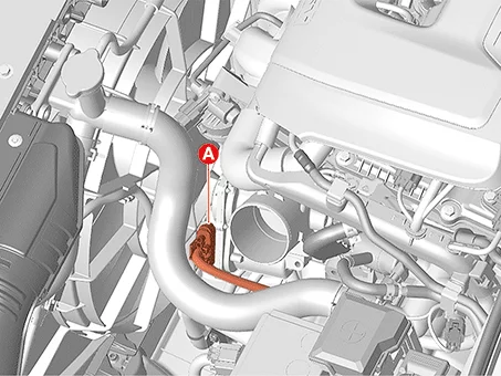
|
| 3. |
Start the engine and measure the output voltage of TPS 1 and 2 at E.C.P and W.O.T.
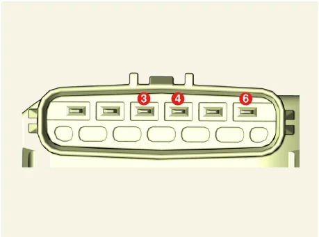
Terminal
|
Function
|
3
|
Sensor ground
|
4
|
Sensor 2
|
6
|
Sensor 1
|
Item
|
Specification
|
Sensor Output Voltage (V)
|
Throttle angle (°)
|
TPS 1
|
TPS 2
|
0
|
0.5
|
4.5
|
10
|
0.96
|
4.05
|
20
|
1.41
|
3.59
|
30
|
1.87
|
3.14
|
40
|
2.32
|
2.68
|
50
|
2.78
|
2.23
|
60
|
3.23
|
1.77
|
70
|
3.69
|
1.32
|
80
|
4.14
|
0.86
|
90
|
4.60
|
0.41
|
98
|
4.65
|
0.35
|
*E.C.P (0°)
|
0.5
|
4.5
|
*W.O.T (86°)
|
4.41
|
0.59
|
*E.C.P : Electrically Close Position
*W.O.T : Wide Open Throttle
|
| Electronic Throttle Control (ETC) Motor |
| 1. |
Disconnect the electronic throttle control (ETC) connector (A).
|
| 2. |
Measure resistance between the ETC module terminals 1 and 2 after disconnecting the connector.
Coil resistance (Ω) : 0.3 - 100 [20°C (68°F)]
|
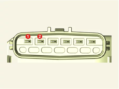
Terminal
|
Function
|
1
|
Motor ( - )
|
2
|
Motor ( + )
|
|
Electronic Throttle Control (ETC) Module Removal and Installation
| 1. |
Disconnect the battery negative ( - ) terminal.
|
| 2. |
Remove the air cleaner assembly.
(Refer to Engine Mechanical System - "Air Cleaner")
|
| 3. |
Disconnect the ETC module connector (A).
|
| 4. |
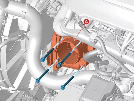
Remove the ETC module (A) by removing the bolts.
Tightening torque :
9.8 - 11.8 N·m (1.0 - 1.2 kgf·m, 7.2 - 8.7 lb·ft)
|
|
| 1. |
Install in reverse order of removal.
|
•
|
Install the Electronic Throttle Control (ETC) module to the specified torque.
|
|
•
|
If the ETC module is dropped, it may cause internal damage. (Do not reuse)
|
|
•
|
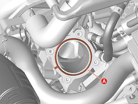
Replace with a new gasket (A) and check to verify that the gasket seats properly before
Installation.
|
|
|
| 2. |
Reset the Engine Control Module (ECM) adaptive values after replacing the ETC.
(S/W Management → Engine Control → Resetting Adaptive Values)
|
Refer to the KDS screen for operating conditions and details
|
|
| 3. |
Perform the Electronic Throttle Control (ETC) module learning procedure.
(Refer to Electronic Throttle Control (ETC) Module - "Adjustment")
|
Electronic Throttle Control (ETC) Module Adjustment
|
•
|
Must perform the Electronic Throttle Control (ETC) learning procedure after replacing or
reinstalling the ETC.
|
|
•
|
If not performing the ETC learning procedure after replacing or re-installing, MIL or DTCs might
occur.
|
|
| 1. |
Wait for 1 minute with the IG ON.
|
| 2. |
Start the engine and keep the idle status for 15 minutes.
|
| 3. |
Waif for 1 minute with the IG OFF.
|
| 4. |
Restart the engine, check that the idle speed is stable.
|
Electronic Throttle Control (ETC) Module Cleaning
| 1. |
Remove the Electronic Throttle Control (ETC) module.
(Refer to Electronic Throttle Control (ETC) Module - "Removal and
Installation")
|
Cleaning the ETC after removing it.
|
|
| 2. |
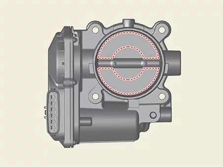
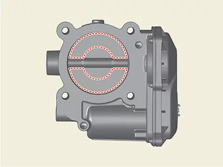
Using a cleaner and soft cloth to clean the contaminated area inside the throttle body.
|
•
|
Be careful not to get foreign matter into the ETC.
|
|
•
|
Do not spray cleaning fluid to ETC directly and use a lint free cloth moistened with
throttle cleaning fluid.
|
|
•
|
Be careful as fingers or cloth may get caught in the valve.
|
|
•
|
Be careful not to wipe the coating liquid (displayed area) around the shaft. If the
coating liquid is removed, a poor idle control may occur due to the inflow of foreign
matters into the shaft inner bearing and an excessive amount of air leaking.
|
|
|
| 3. |
Install the ETC module.
(Refer to Electronic Throttle Control (ETC) Module - "Removal and
Installation")
|
Engine Control Module (ECM) Components and Components Location
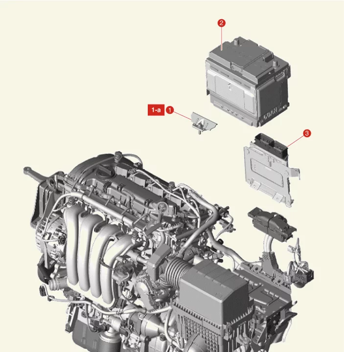
1. Battery Clamp
1-a. 8.8 - 13.7 N·m (0.9 -
1.4 kgf·m, 6.5 - 10.1 lb·ft)
|
2. Battery
3. Engine Control Module (ECM)
|
Engine Control Module (ECM) On Vehicle Inspection
| 1. |
The engine control system can be more quickly diagnosed for problems by using the KDS (Refer to "DTC
guide").
| (1)
|
Self diagnosis : Inspect the Diagnostic Trouble Code (DTC) using the KDS
(Refer to DTC guide when fault code is found)
|
| (2)
|
S/W Management : Controlling other features including system option setting and zero point
adjustment
(S/W Management → Engine Control → Resetting Adaptive Values)
|
|
Refer to the KDS screen for operating conditions and details
|
|
Engine Control Module (ECM) Removal and Installation
| 1. |
Perform the IVT oil pressure characteristics backup procedure using the KDS when replacing with a new
ECM.
| (1)
|
Select the "Oil-pressure Characteristics input" in the S/W Management of KDS.
|
|
| 2. |
Remove the battery.
(Refer to Engine Electrical System - "Battery")
|
| 3. |
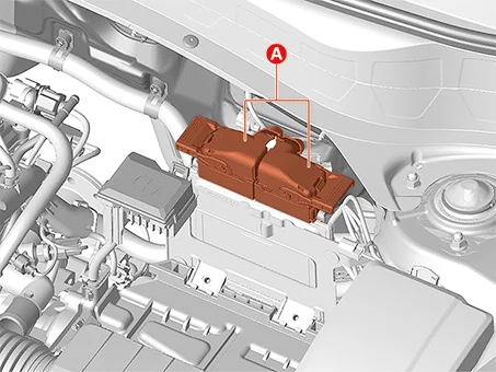
Disconnect the Engine Control Module (ECM) connectors (A).
|
| 4. |
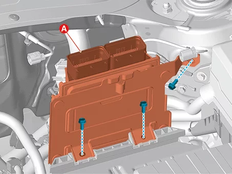
Remove the ECM (A) after removing the bolts.
Tightening torque :
9.8 - 11.8 N·m (1.0 - 1.2 kgf·m, 7.2 - 8.7 lb·ft)
|
|
| 5. |
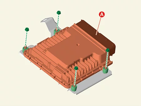
Remove the ECM (A) from the bracket after removing the nuts.
Tightening torque :
9.8 - 11.8 N·m (1.0 - 1.2 kgf·m, 7.2 - 8.7 lb·ft)
|
|
| 1. |
Install in reverse order of removal.
|
•
|
Install the Engine Control Module (ECM) to the specified torque.
|
|
•
|
If the ECM is dropped, it may cause internal damage. (Do not reuse)
|
|
|
| 2. |
ECM should be performed the reset and learning procedure after replacing it with a new one.
(Refer to Engine Control Module (ECM) - "Adjustment")
|
Engine Control Module (ECM) Inspection
| 1. |
TEST Engine Control Module (ECM) GROUND CIRCUIT: Measure resistance between ECM and chassis ground using
the backside of ECM harness connector as ECM side check point. If the problem is found, repair it.
Specification : 1 Ω or less
|
|
| 2. |
TEST ECM CONNECTOR: Disconnect the ECM connector and visually check the ground terminals on ECM side and
harness side for bent pins or poor contact pressure. If the problem is found, repair it.
|
| 3. |
If problem is not found in Step 1 and 2, the ECM could be faulty. If so, replace the ECM with a new one,
and then check the vehicle again. If the vehicle operates normally then the problem was likely with the ECM.
|
| 4. |
RE-TEST THE ORIGINAL ECM : Install the original ECM (may be broken) into a known-good vehicle and check
the vehicle. If the problem occurs again, replace the original ECM with a new one. If problem does not
occur, this is intermittent problem (Refer to Intermittent Problem Procedure in Basic Inspection Procedure)
|
Engine Control Module (ECM) Adjustment
|
Perform inspecting procedure by using the KDS as below order.
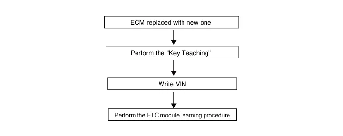
|
| 1. |
Perform the procedures below by using the KDS when replacing the Engine Control Module (ECM) with a
reused one.
|
Refer to the KDS screen for operating conditions and details
|
| (1)
|
Perform the resetting adaptive values.
(S/W Management → Engine Control → Resetting Adaptive Values)
|
| (2)
|
Perform the immobilizer neutral mode / smart key neutralization mode.
|
•
|
Non-Smart Key type
(S/W Management → Immobilizer → Neutral Mode)
|
|
•
|
Smart Key type
(S/W Management → Smart Key Unit → Neutralization Mode)
|
|
| (3)
|
Perform the auto detected configuration reset.
(S/W Management → Engine Control → Auto Detected Configuration Reset)
|
|
| 2. |
Perform the "Key Teaching" procedure by using the KDS.
|
•
|
Non-Smart Key type
(S/W Management → Immobilizer → LEARNT KEYS)
|
|
•
|
Smart Key type
Turn IG ON then OFF using the smart key or start button. Then the ECM learns information on the
smart key automatically.
|
|
| 3. |
Perform the VIN writing procedure by using the KDS.
(S/W Management → Engine Control → Write VIN)
|
| 4. |
Perform the Electronic Throttle Control (ETC) module learning procedure.
(Refer to Engine Control / Fuel System - "Electronic Throttle Control
(ETC) Module")
|
Engine Coolant Temperature Sensor (ECTS) Specification
Temperature
|
Resistance (kΩ)
|
°C
|
°F
|
-40
|
-40
|
48.14
|
-20
|
-4
|
14.13 - 16.83
|
0
|
32
|
5.79
|
20
|
68
|
2.31 - 2.59
|
40
|
104
|
1.148
|
60
|
140
|
0.5865
|
80
|
176
|
0.3222
|
100
|
212
|
0.1884
|
110
|
230
|
0.1451 - 0.1473
|
120
|
248
|
0.1163
|
Engine Coolant Temperature Sensor (ECTS) Components and Components Location
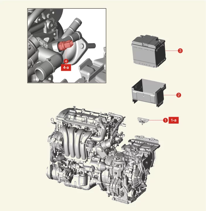
1. Battery Clamp
1-a. 8.8 - 13.7 N·m (0.9 - 1.4
kgf·m, 6.5 - 10.1 lb·ft)
2. Battery Insulation Pad
|
3. Battery
4. Engine Coolant Temperature Sensor
(ECTS)
4-a. 19.6 - 39.2 N·m (2.0 - 4.0 kgf·m, 14.5 - 28.9 lb·ft)
|
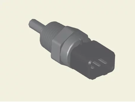
Engine Coolant Temperature Sensor (ECTS) Description and Operation
|
•
|
Engine Coolant Temperature Sensor (ECTS) detects the engine coolant temperature.
|
|
•
|
The thermistor of ECTS has a characteristic of Negative Temperature Coefficient (NTC), which means
temperature and resistance are inversely proportional to each other.
|
|
•
|
The reference +5 V is supplied to the ECTS via a resistor in the Engine Control Module (ECM). That is,
the resistor in the ECM and the thermistor in the ECTS are connected in series.
|
|
•
|
To prevent the engine stop or hesitation during the cold start, the ECM calibrates the fuel injection
amount and the injection timing based on the engine coolant temperature information.
|
Engine Coolant Temperature Sensor (ECTS) On Vehicle Inspection
| 1. |
The engine control system can be more quickly diagnosed for problems by using the KDS (Refer to "DTC
guide").
| (1)
|
Self diagnosis : Inspect the Diagnostic Trouble Code (DTC) using the KDS
(Refer to DTC guide when fault code is found)
|
Refer to the KDS screen for operating conditions and details
|
|
|
| 1. |
Check the coolant temperature by using the KDS.
|
| 2. |
Disconnect the Engine Coolant Temperature Sensor (ECTS) connector (A).
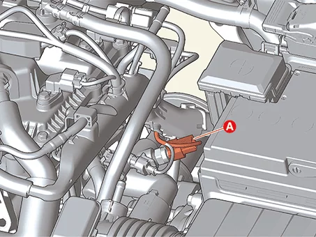
|
| 3. |
Measure resistance after disconnecting the ECTS connector.
Temperature
|
Resistance (kΩ)
|
°C
|
°F
|
-40
|
-40
|
48.14
|
-20
|
-4
|
14.13 - 16.83
|
0
|
32
|
5.79
|
20
|
68
|
2.31 - 2.59
|
40
|
104
|
1.148
|
60
|
140
|
0.5865
|
80
|
176
|
0.3222
|
100
|
212
|
0.1884
|
110
|
230
|
0.1451 - 0.1473
|
120
|
248
|
0.1163
|
|
Engine Coolant Temperature Sensor (ECTS) Removal and Installation
| 1. |
Disconnect the battery negative ( - ) terminal.
|
| 2. |
Drain the coolant.
(Refer to Engine Mechanical System - "Coolant")
|
| 3. |
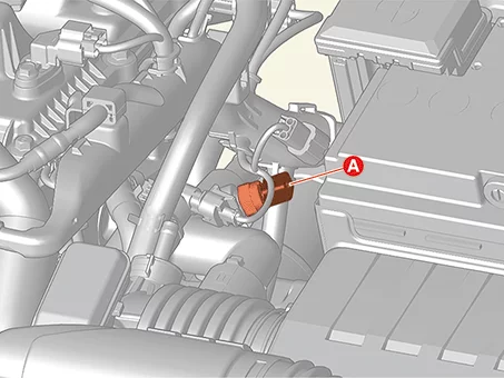
Disconnect the Engine Coolant Temperature Sensor (ECTS) connector (A).
|
| 4. |
Remove the ECTS (A).
Tightening torque :
19.6 - 39.2 N·m (2.0 - 4.0 kgf·m, 14.5 - 28.9 lb·ft)
|
|
| 1. |
Install in reverse order of removal.
|
•
|
Install the Engine Coolant Temperature Sensor (ECTS) to the specified torque.
|
|
•
|
If the ECTS is dropped, it may cause internal damage. (Do not reuse)
|
|
•
|
Apply the engine coolant to the O-ring.
|
|
•
|
Install the ECTS by pushing it into the mounting hole when installing it. At this time do
not impact the sensor.
|
|
|
| 2. |
Refill with coolant.
(Refer to Engine Mechanical System - "Coolant")
|
Heated Oxygen Sensor (HO2S) Specification
| Front Heated Oxygen Sensor |
Item
|
Specification
|
Operating voltage (V)
|
12
|
Heater resistance (Ω)
|
2.5 (Room temperature)
|
Heater control frequency (Hz)
|
≥100
|
Heater capacity (W)
|
8.1
|
Current consumption (A)
|
1.2
|
| Rear Heated Oxygen Sensor |
Item
|
Specification
|
Operating voltage (V)
|
12
|
Heater resistance (Ω)
|
3 (Room temperature)
|
Heater control frequency (Hz)
|
≥10
|
Heater capacity (W)
|
7
|
Current consumption (A)
|
1.5
|
Heated Oxygen Sensor (HO2S) Components and Components Location
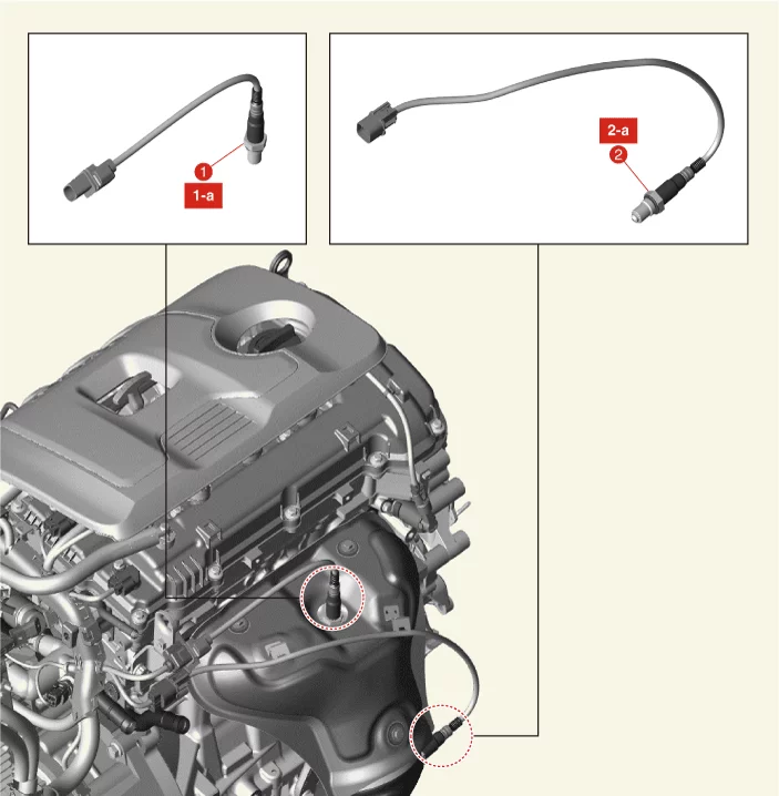
1. Front Heated Oxygen Sensor (HO2S)
1-a. 39.3 -
49.0 N·m (4.0 - 5.0 kgf·m, 29.0 - 36.1 lb·ft)
|
2. Rear Heated Oxygen Sensor (HO2S)
2-a. 39.3 -
49.0 N·m (4.0 - 5.0 kgf·m, 29.0 - 36.1 lb·ft)
|
Heated Oxygen Sensor (HO2S) Description and Operation
|
•
|
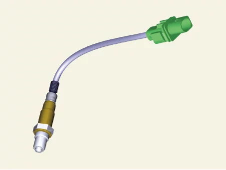
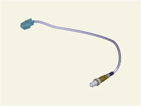
Heated Oxygen Sensor (HO2S), consisting of zirconium and alumina, is installed on both upstream and
downstream of the Manifold Catalytic Converter (MCC) to detect the air/fuel ratio and send it to the Engine
Control Module (ECM).
|
|
•
|
In order that this sensor operates properly, the temperature of the sensor tip must be higher than 370°C
(698°F). For this reason, a heater controlled by the ECM duty signal, is built into the sensor.
|
|
•
|
When the exhaust gas temperature is lower than the specified value, the heater warms the sensor tip.
|
|
Front
|
|
Rear
|
Heated Oxygen Sensor (HO2S) On Vehicle Inspection
| 1. |
The engine control system can be more quickly diagnosed for problems by using the KDS (Refer to "DTC
guide").
| (1)
|
Self diagnosis : Inspect the Diagnostic Trouble Code (DTC) using the KDS
(Refer to DTC guide when fault code is found)
|
| (2)
|
Data analysis : Checking the system input/output data state
(Data Analysis → System Selection → Engine)
|
|
Refer to the KDS screen for operating conditions and details
|
|
Component Inspection
| 1. |
Disconnect the Heated Oxygen Sensor (HO2S) connector (A).
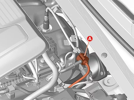
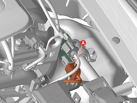
|
| 2. |
Measure resistance between the HO2S terminals.
Front Heated Oxygen Sensor
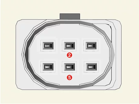
Terminal
|
Function
|
2
|
Heater ( + )
|
5
|
Heater ( - )
|
Rear Heated Oxygen Sensor
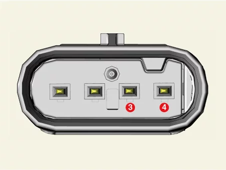
Terminal
|
Function
|
3
|
Heater ( + )
|
4
|
Heater ( - )
|
|
| 3. |
Check that the resistance is within the specification.
Item
|
Specification
|
Front heated oxygen sensor (Ω)
|
2.5 (Room temperature)
|
Rear heated oxygen sensor (Ω)
|
3.0 (Room temperature)
|
|
Heated Oxygen Sensor (HO2S) Removal and Installation
Tool Name / Number
|
Illustration
|
Description
|
Heated oxygen sensor socket
09392 - 1Y100
|
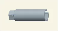
|
Used for removing / installing the heated oxygen sensor
※ SST 09392 - 2H100 also can be used
|
|
Wait until cooling the engine for preventing the scalding by high temperature from the exhaust system.
|
Front Heated Oxygen Sensor (HO2S)
| 1. |
Disconnect the battery negative ( - ) terminal.
|
| 2. |
Disconnect the front Heated Oxygen Sensor (HO2S) connector (A).
|
| 3. |
Separate the front HO2S connector (A) by pulling it in the direction of the arrow from the bracket.
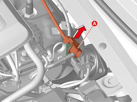
|
| 4. |
Remove the front HO2S (A) by using the SST.
Tightening torque :
39.2 - 49.0 N·m (4.0 - 5.0 kgf·m, 28.9 - 36.2 lb·ft)
|
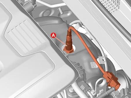
|
Rear Heated Oxygen Sensor (HO2S)
| 1. |
Disconnect the battery negative ( - ) terminal.
|
| 2. |
Disconnect the rear Heated Oxygen Sensor (HO2S) connector (A).
|
| 3. |
Separate the rear HO2S connector (A) by pulling it in the direction of the arrow from the bracket.
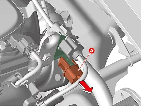
|
| 4. |
Separate the rear HO2S wiring (A) from the fixing clips.
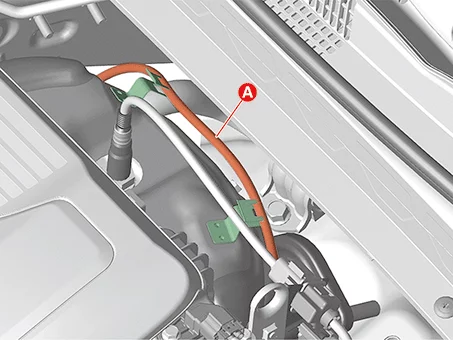
|
| 5. |
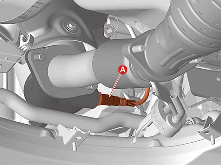
Remove the rear HO2S (A).
Tightening torque :
39.2 - 49.0 N·m (4.0 - 5.0 kgf·m, 28.9 - 36.2 lb·ft)
|
|
| 1. |
Install in reverse order of removal.
|
•
|
Install the Heated Oxygen Sensor (HO2S) to the specified torque.
|
|
•
|
If HO2S is dropped, it may cause internal damage. (Do not reuse)
|
|
•
|
Do not use oil components such as cleaners, sprays, or greases on the sensing part and
connector as it may degrade the performance of HO2S.
|
|
•
|
The sensor or the wiring can be damaged by being contacted to the exhaust system (Exhaust
manifold, Catalytic converter etc.).
|
|
|
| 2. |
Reset the ECM adaptive value after replacing the heated oxygen sensor.
(S/W Management → Engine → Resetting Adaptive Values)
|
Refer to the KDS screen for operating conditions and details
|
|
Intake Middle Lock Control Solenoid Components and Components Location
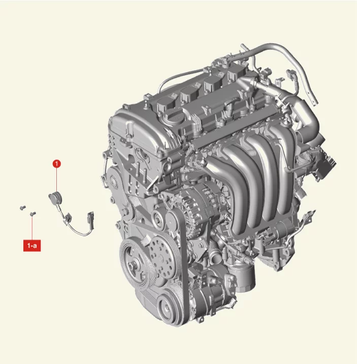
1. Intake Middle Lock Control Solenoid
1-a. 8.8 -
9.8 N·m (0.9 - 1.0 kgf·m, 6.5 - 7.2 lb·ft)
|
Intake Middle Lock Control Solenoid Description and Operation
|
•
|
The Continuous Variable Valve Timing (CVVT) system uses Engine Control Module (ECM) control signals that
vary with engine RPM and load to advance or retard the timing of opening/closing the intake or exhaust
valve.
|
|
•
|
According to the valve overlap and underlap between the intake and exhaust valve by CVVT, there are
effects such as reduce the pumping loss, occur internal EGR and improve the combustion stability and
volumetric efficiency. For these reasons, fuel efficiency and engine performance are improved, and the
exhaust gas (NOx, HC) decreases.
|
|
•
|
The CVVT Oil Control Valve (OCV) supplies or discharges the oil to a cam phaser by changing the path of
engine oil, receiving the PWM (Pulse Width Modulation) signal of ECM.
|
|
•
|
The oil from the OCV changes the phase of the cam shaft by advancing or retarding the cam shaft by
rotating the rotor connected to the cam shaft inside the cam phaser.
|
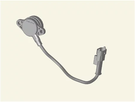
Intake Middle Lock Control Solenoid On Vehicle Inspection
| 1. |
The engine control system can be more quickly diagnosed for problems by using the KDS (Refer to "DTC
guide").
| (1)
|
Self diagnosis : Inspect the Diagnostic Trouble Code (DTC) using the KDS
(Refer to DTC guide when fault code is found)
|
|
Refer to the KDS screen for operating conditions and details
|
|
Intake Middle Lock Control Solenoid Removal and Installation
| 1. |
Disconnect the battery negative ( - ) terminal.
|
| 2. |
Remove the engine cover.
(Refer to Engine Mechanical System - "Engine Cover")
|
| 3. |
Disconnect the intake middle lock control solenoid connector (A).
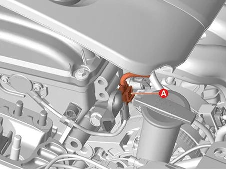
|
| 4. |
Separate the connector (A) from the bracket and separate the fixing holder (B).
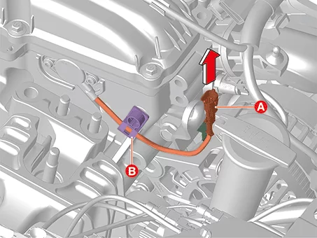
|
| 5. |
Remove the intake middle lock control solenoid (A) after removing the screws.
Tightening torque :
8.8 - 9.8 N·m (0.9 - 1.0 kgf·m, 6.5 - 7.2 lb·ft)
|
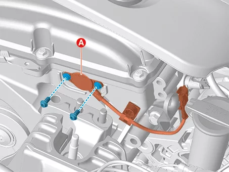
|
| 1. |
Install in reverse order of removal.
|
•
|
Install the intake middle lock control solenoid to the specified torque.
|
|
•
|
If the intake middle lock control solenoid is dropped, it may cause internal damage. (Do
not reuse)
|
|
•
|
Apply the engine oil to the O-ring.
|
|
|
Knock Sensor (KS) Specification
Item
|
Specification
|
Capacitance (pF)
|
850 - 1,150
|
Knock Sensor (KS) Components and Components Location
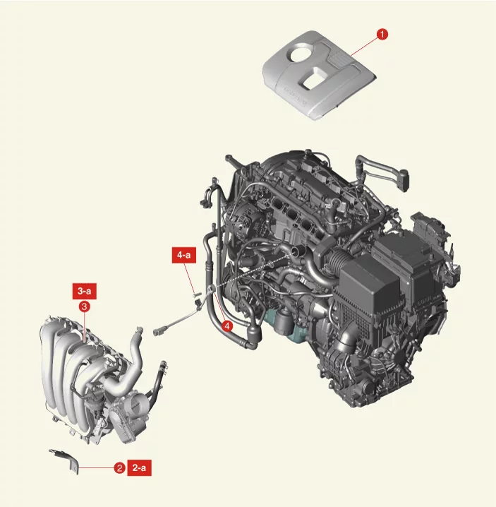
1. Engine Cover
2. Intake Manifold Bracket
2-a.
18.6 - 23.5 N·m (1.9 - 2.4 kgf·m, 13.7 - 17.4 lb·ft)
|
3. Intake Manifold
3-a. 18.6 - 23.5 N·m (1.9 - 2.4
kgf·m, 13.7 - 17.4 lb·ft)
4. Knock Sensor (KS)
4-a. 18.6 - 23.5 N·m (1.9 - 2.4 kgf·m, 13.7 - 17.4
lb·ft)
|
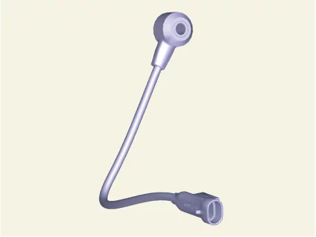
Knock Sensor (KS) Description and Operation
|
•
|
The Knock Sensor (KS) detects vibration when knocking and transmits to the Engine Control Module (ECM).
|
|
•
|
The knocking sensor outputs a knocking signal when knocking, and the ECM that receives the signal to
prevent the knocking by perceiving the timing of ignition. If there is no knocking signal, ECM which
controls the timing of ignition continuously to ensure the optimum torque and fuel efficiency.
|
Knock Sensor (KS) On Vehicle Inspection
| 1. |
The engine control system can be more quickly diagnosed for problems by using the KDS (Refer to "DTC
guide").
| (1)
|
Self diagnosis : Inspect the Diagnostic Trouble Code (DTC) using the KDS
(Refer to DTC guide when fault code is found)
|
| (2)
|
Data analysis : Checking the system input/output data state
(Data Analysis → System Selection → Engine)
|
|
Refer to the KDS screen for operating conditions and details
|
|
| 1. |
Check signal waveform of Knock Sensor (KS) by using a KDS.
Specified value : Refer to "DTC diagnostic guide"
|
|
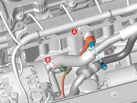
Knock Sensor (KS) Removal and Installation
| 1. |
Remove the intake manifold.
(Refer to Engine Mechanical System - "Intake Manifold")
|
| 2. |
Remove the Knock Sensor (KS) (A) after removing the fixing clip (B).
Tightening torque :
18.6 - 23.5 N·m (1.9 - 2.4 kgf·m, 13.7 - 17.4 lb·ft)
|
|
| 1. |
Install in reverse order of removal.
|
•
|
Install the Knock Sensor (KS) to the specified torque.
|
|
•
|
If the KS is dropped, it may cause internal damage. (Do not reuse)
|
|
|
Manifold Absolute Pressure Sensor & Intake Air Temperature Sensor (MAPS & IATS) Specification
Item
|
Specification
|
Rated voltage (V)
|
5
|
Operating voltage (V)
|
4.75 - 5.25
|
Current consumption (mA)
|
10
|
Pressure [kPa (kg/cm², psi)]
|
20 - 101.32 (0.2 - 1.03, 2.9 - 14.70)
|
Pressure Signal
Pressure
|
Output Voltage (V)
|
kPa
|
kg/cm²
|
psi
|
20
|
0.20
|
2.90
|
0.789
|
46.66
|
0.48
|
6.78
|
1.842
|
101.32
|
1.03
|
14.70
|
4.000
|
Manifold Absolute Pressure Sensor & Intake Air Temperature Sensor (MAPS & IATS) Components and Components
Location
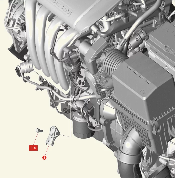
1. Manifold Absolute Pressure Sensor & Intake Air
Temperature Sensor (MAPS & IATS)
1-a. 9.8 - 11.8 N·m (1.0 - 1.2 kgf·m, 7.2 - 8.7 lb·ft)
|
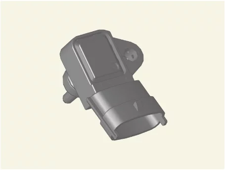
Manifold Absolute Pressure Sensor & Intake Air Temperature Sensor (MAPS & IATS) Description and Operation
| Manifold Absolute Pressure Sensor (MAPS) |
|
•
|
Manifold Absolute Pressure Sensor (MAPS) is a speed-density type sensor that senses absolute pressure of
the Intake Manifold.
|
|
•
|
MAPS transfers the analog signal proportional to the pressure to the Engine Control Module (ECM).
|
|
•
|
By using this signal, the ECM calculates the intake air amount and engine speed.
|
| Intake Air Temperature Sensor (IATS) |
|
•
|
Intake Air Temperature Sensor (IATS) is included inside MAPS and detects the intake air temperature.
|
|
•
|
To calculate precise air quantity, correction of the air temperature is needed because air density varies
according to the temperature. So the ECM uses not only MAPS signal but also IATS signal.
|
|
•
|
This sensor has a Negative Temperature Coefficient (NTC) Thermistor and it's resistance changes in
reverse proportion to the temperature.
|
Manifold Absolute Pressure Sensor & Intake Air Temperature Sensor (MAPS & IATS) On Vehicle Inspection
| 1. |
The engine control system can be more quickly diagnosed for problems by using the KDS (Refer to "DTC
guide").
| (1)
|
Self diagnosis : Inspect the Diagnostic Trouble Code (DTC) using the KDS
(Refer to DTC guide when fault code is found)
|
| (2)
|
Data analysis : Checking the system input/output data state
(Data Analysis → System Selection → Engine)
|
|
Refer to the KDS screen for operating conditions and details
|
|
Manifold Absolute Pressure Sensor & Intake Air Temperature Sensor (MAPS & IATS) Removal and Installation
| 1. |
Disconnect the battery negative ( - ) terminal.
|
| 2. |
Remove the air cleaner assembly.
(Refer to Engine Mechanical System - "Air Cleaner")
|
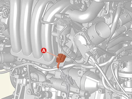
| 3. |
Disconnect the Manifold Absolute Pressure Sensor & Intake Air Temperature Sensor (MAPS & IATS)
connector (A).
|
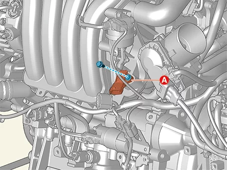
| 4. |
Remove the MAPS & IATS (A) after removing the bolt.
Tightening torque :
9.8 - 11.8 N·m (1.0 - 1.2 kgf·m, 7.2 - 8.7 lb·ft)
|
|
| 1. |
Install in reverse order of removal.
|
•
|
Install the Manifold Absolute Pressure Sensor & Intake Air Temperature Sensor (MAPS
& IATS) to the specified torque.
|
|
•
|
If the MAPS & IATS is dropped, it may cause internal damage. (Do not reuse)
|
|
|
Oil Pressure Sensor (OPS) Specification
Item
|
Specification
|
Rated voltage (V)
|
12
|
Operating pressure [kgf / cm² (kPa, psi)]
|
0.2 - 0.4 (19.61 - 39.22, 2.84 - 5.68)
|
Load (W)
|
Maximum 5
|
Oil Pressure Sensor (OPS) Components and Components Location
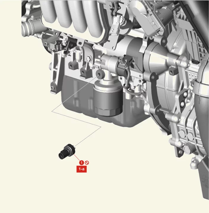
1. Oil Pressure Sensor (OPS)
1-a. 9.8 - 11.8 N·m
(1.0 - 1.2 kgf·m, 7.2 - 8.7 lb·ft)
|
Oil Pressure Sensor (OPS) On Vehicle Inspection
| 1. |
The engine control system can be more quickly diagnosed for problems by using the KDS (Refer to "DTC
guide").
| (1)
|
Self diagnosis : Inspect the Diagnostic Trouble Code (DTC) using the KDS
(Refer to DTC guide when fault code is found)
|
|
Refer to the KDS screen for operating conditions and details
|
|
Oil Pressure Sensor (OPS) Removal and Installation
| 1. |
Disconnect the battery negative ( - ) terminal.
|
| 2. |
Remove the engine compartment under cover.
(Refer to Engine Mechanical System - "Engine Room Under Cover")
|
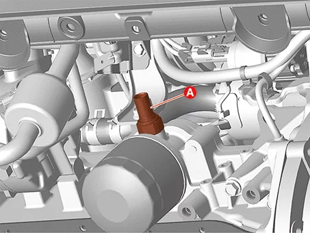
| 3. |
Disconnect the Oil Pressure Sensor (OPS) connector (A).
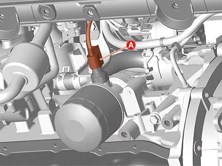
|
| 4. |
Remove the OPS (A).
Tightening torque :
9.8 - 11.8 N·m (1.0 - 1.2 kgf·m, 7.2 - 8.7 lb·ft)
|
|
| 1. |
Install in reverse order of removal.
|
•
|
Install the Oil Pressure Sensor (OPS) to the specified torque.
|
|
•
|
If the OPS is dropped, it may cause internal damage. (Do not reuse)
|
|
•
|
Be careful not to get engine oil and/or coolant flow into the OPS connector.
|
|
•
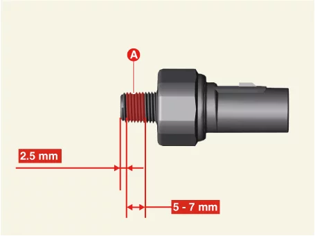
|
Apply the seal lock to part (A) when installing the OPS.
Thickness : 0.2 - 0.4 mm (0.0078 - 0.0157
in)
|
|
|
|
Variable Charge Motion Actuator (VCMA) Components and Components Location
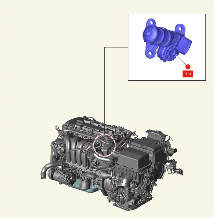
1. Variable Charge Motion Actuator (VCMA)
1-a. 9.8
- 11.8 N·m (1.0 - 1.2 kgf·m, 7.2 - 8.7 lb·ft)
|
|
Variable Charge Motion Actuator (VCMA) Removal and Installation
| 1. |
Disconnect the battery negative ( - ) terminal.
|
| 2. |
Remove the engine cover.
(Refer to Engine Mechanical System - "Engine Cover")
|
| 3. |
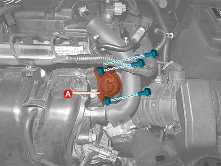
Disconnect the Variable Charge Motion Actuator (VCMA) connector (A).
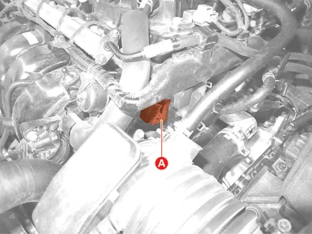
|
| 4. |
Remove the VCMA (A) after removing the bolts.
Tightening torque :
9.8 - 11.8 N·m (1.0 - 1.2 kgf·m, 7.2 - 8.7 lb·ft)
|
|
| 1. |
Install in reverse order of removal.
|
•
|
Install the Variable Charge Motion Actuator (VCMA) to the specified torque.
|
|
•
|
If the VCMA is dropped, it may cause internal damage. (Do not reuse)
|
|
|
Variable Intake Solenoid (VIS) Valve Specification
Item
|
Specification
|
Operating voltage (V)
|
9 - 16 [22°C (71.6°F)]
|
Coil resistance (Ω)
|
30 - 35 [22°C (71.6°F)]
|
Variable Intake Solenoid (VIS) Valve Components and Components Location
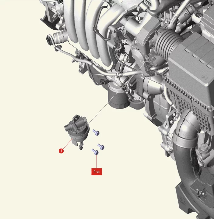
1. Variable Intake Solenoid (VIS) Valve
1-a. 9.8 -
11.8 N·m (1.0 - 1.2 kgf·m, 7.2 - 8.7 lb·ft)
|
Variable Intake Solenoid (VIS) Valve Description and Operation
|
•
|
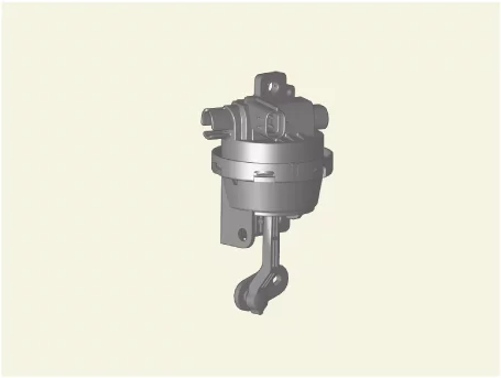
The Variable Intake Solenoid (VIS) valve works as controlling the vacuum valve in intake manifold.
|
|
•
|
This valve is controlled by the Engine Control Module (ECM) control signal according to the engine
driving condition.
|
Variable Intake Solenoid (VIS) Valve On Vehicle Inspection
| 1. |
The engine control system can be more quickly diagnosed for problems by using the KDS (Refer to "DTC
guide").
| (1)
|
Self diagnosis : Inspect the Diagnostic Trouble Code (DTC) using the KDS
(Refer to DTC guide when fault code is found)
|
| (2)
|
Actuation test : Checking the system operation condition
(Data Analysis → System Selection → Engine → Actuation test → Variable Intake Manifold (Both ECU
Output))
|
|
Refer to the KDS screen for operating conditions and details
|
|
Component Inspection
| 1. |
Turn the ignition switch OFF.
|
| 2. |
Disconnect the Variable Intake Solenoid (VIS) Valve connector.
|
| 3. |
Measure resistance between VIS valve terminals.
Item
|
Specification
|
Coil resistance (Ω)
|
30 - 35 [22°C (71.6°F)]
|
|
Variable Intake Solenoid (VIS) Valve Removal and Installation
| 1. |
Disconnect the battery negative ( - ) terminal.
|
| 2. |
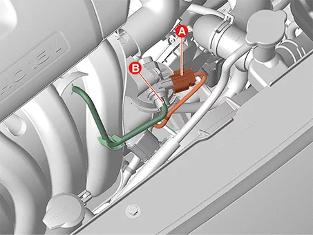
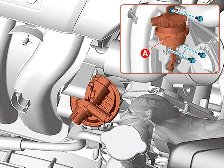
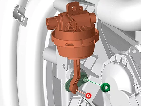
Disconnect the Variable Intake Solenoid (VIS) valve connector (A) and vacuum hose (B).
|
| 3. |
Remove the VIS valve (A) after removing the bolts and nut.
Tightening torque :
9.8 - 11.8 N·m (1.0 - 1.2 kgf·m, 7.2 - 8.7 lb·ft)
|
|
| 1. |
Install in reverse order of removal.
|
•
|
Install the Variable Intake Solenoid (VIS) valve to the specified torque.
|
|
•
|
If the VIS valve is dropped, it may cause internal damage. (Do not reuse)
|
|
•
|
Be careful not to get foreign matters into the VIS valve.
|
|
|



