
Kia Seltos SP2 (2021-2026) Service Manual / Body Electrical System / Integrated Body Control Unit (IBU)
Kia Seltos: Body Electrical System / Integrated Body Control Unit (IBU)
Contents:
Description and Operation ➤
On Vehicle Inspection
| On Vehicle Inspection |
| Diagnosis with KDS |
| 1. |
The Integrated Body Control Unit (IBU) can be more quickly diagnosed for problems with the KDS (Refer to
"DTC guide").
|

Terminal Function
| Connector and Terminal Function |
[Non-Smart Key Type]
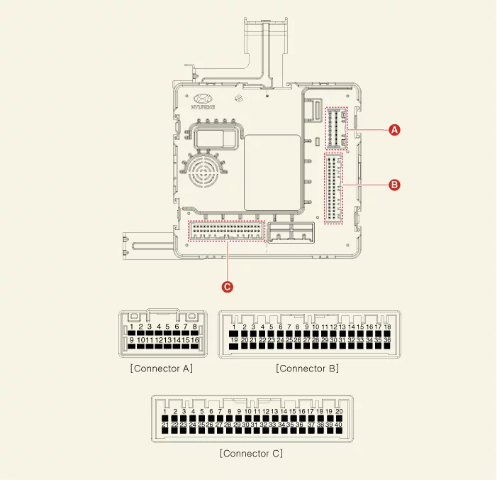
| Terminal |
Function |
||
|
Connector A |
Connector B |
Connector C |
|
|
1 |
- |
- |
- |
|
2 |
Front heated nozzle (output) |
- |
- |
|
3 |
Rear washer switch (input) |
- |
Outside mirror folding (output) |
|
4 |
Front washer switch (input) |
LIN2 (Safety ECU) |
PDW Option (input) |
|
5 |
- |
LIN1 (PDW) |
- |
|
6 |
Ground (power) |
PDW-R power (input) |
- |
|
7 |
Ground (ECU) |
PDW-R power (output) |
- |
|
8 |
- |
PDW-F power (output) |
- |
|
9 |
Battery ( + ) ECU |
ATM solenoid (output) |
Auto light sensor ground (output) |
|
10 |
Battery ( + ) power |
Headlamp high switch (input) |
RVM switch (input) |
|
11 |
IG1 (input) |
Front wiper switch (input) |
PDW-R switch (input) |
|
12 |
Kline immobilizer |
Front wiper volume switch (input) |
Key interlock switch (input) |
|
13 |
- |
Wiper parking switch (input) |
- |
|
14 |
- |
- |
Multifunction switch ground (input) |
|
15 |
- |
PDW-R Indicator (output) |
ACC (input) |
|
16 |
- |
- |
IGN2 (input) |
|
17 |
- |
Front wiper low back-up switch (input) |
|
|
18 |
- |
Brake switch (input) |
|
|
19 |
- |
- |
|
|
20 |
- |
- |
|
|
21 |
- |
- |
|
|
22 |
LIN3 (Rain sensor) |
- |
|
|
23 |
- |
Outside mirror unfolding (output) |
|
|
24 |
- |
- |
|
|
25 |
Front wiper low relay (output) |
B-CAN (High) |
|
|
26 |
Front wiper high relay (output) |
B-CAN (Low) |
|
|
27 |
Rear wiper relay (output) |
P-CAN (High) |
|
|
28 |
Fog lamp switch (input) |
P-CAN (Low) |
|
|
29 |
Light switch (input) |
Auto light sensor power (output) |
|
|
30 |
Rear wiper switch (input) |
Auto light sensor signal (input) |
|
|
31 |
- |
Sunroof status (input) |
|
|
32 |
- |
Key solenoid (output) |
|
|
33 |
Keyhole illumination (output) |
Start inhibit relay (output) |
|
|
34 |
EMS ECU wake up (Output) Door unlock signal (for IFU) output |
Key in switch (input) |
|
|
35 |
- |
- |
|
|
36 |
- |
- |
|
|
37 |
Immobilizer antenna power (output) |
||
|
38 |
Immobilizer antenna ground (output) |
||
|
39 |
- |
||
|
40 |
- |
||
[Smart Key Type]
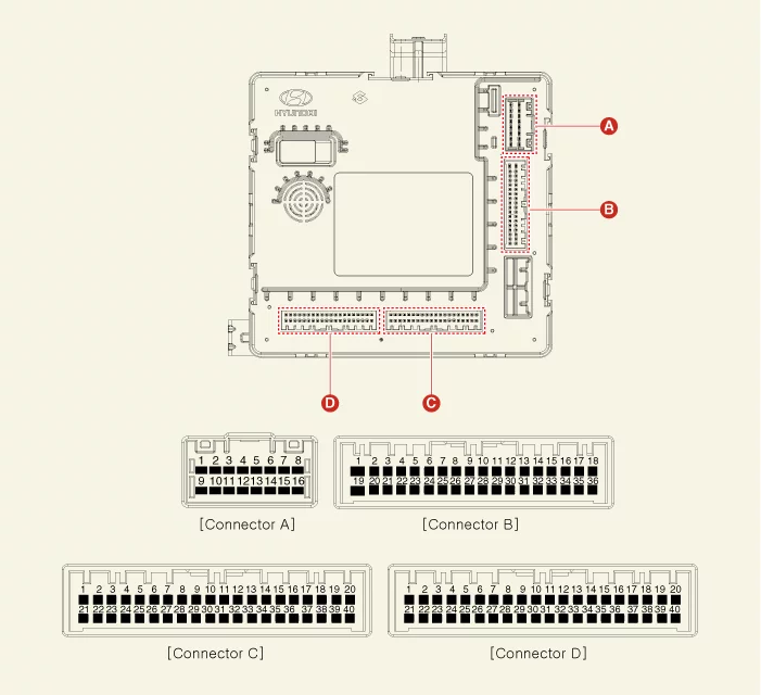
| Terminal |
Function |
|||
|
Connector A |
Connector B |
Connector C |
Connector D |
|
|
1 |
ESCL ( + ) output |
- |
- |
- |
|
2 |
Front heated nozzle (output) |
- |
- |
- |
|
3 |
Rear washer switch (input) |
- |
Outside mirror folding (output) |
- |
|
4 |
Front washer switch (input) |
LIN2 (Safety ECU) |
Passenger's door touch sensor unlock (input) |
- |
|
5 |
- |
LIN1 (PDW) |
- |
ESCL Enable (output) |
|
6 |
Ground (power) |
PDW-R power (input) |
- |
RPM (input) |
|
7 |
Ground (ECU) |
PDW-R power (output) |
- |
Starter relay (output) |
|
8 |
ESCL ( - ) output |
PDW-F power (output) |
- |
ACC relay (output) |
|
9 |
Battery ( + ) ECU |
ATM solenoid (output) |
Auto light sensor ground (output) |
Starter feedback (Input) |
|
10 |
Battery ( + ) power |
Headlamp high switch (input) |
RVM switch (input) |
SSB Switch 2 (input) |
|
11 |
IG1 (input) |
Front wiper switch (input) |
PDW-R switch (input) |
Interior antenna 3 ( - ) output |
|
12 |
Kline immobilizer |
Front wiper volume switch (input) |
AT : 'P' (input) |
Interior antenna 1 ( - ) output |
|
13 |
- |
Wiper parking switch (input) |
Passenger's outside handle touch sensor lock (input) |
- |
|
14 |
- |
Buzzer (output) |
Multifunction switch ground (input) |
Passenger's outside handle antenna ( - ) output |
|
15 |
- |
PDW-R Indicator (Output) |
ACC (input) |
Front bumper antenna ( - ) output |
|
16 |
- |
- |
IG2 (input) |
- |
|
17 |
- |
Front wiper low back-up switch (input) |
Rear bumper antenna ( - ) output |
|
|
18 |
- |
Brake switch (input) |
Driver's outside handle antenna ( - ) output |
|
|
19 |
- |
- |
Immobilizer ground (output) |
|
|
20 |
- |
- |
- |
|
|
21 |
- |
- |
- |
|
|
22 |
LIN3 (Rain sensor) |
PDW Option (input) |
- |
|
|
23 |
- |
Outside mirror unfolding (output) |
- |
|
|
24 |
- |
Driver's door touch sensor unlock (input) |
- |
|
|
25 |
Front wiper low relay (output) |
- |
- |
|
|
26 |
Front wiper high relay (output) |
- |
Wheel speed sensor (input) |
|
|
27 |
Rear wiper relay (output) |
- |
IG2 Relay (output) |
|
|
28 |
Fog lamp switch (input) |
- |
IG1 Relay (output) |
|
|
29 |
Light switch (input) |
Auto light sensor power (output) |
SSB symbol illumination ( + ) output |
|
|
30 |
Rear wiper switch (input) |
Auto light sensor signal (input) |
SSB Switch 1 (input) |
|
|
31 |
- |
Sunroof status (input) |
Interior antenna 3 ( + ) output |
|
|
32 |
- |
ESCl Unlock switch (input) |
Interior antenna 1 ( + ) output |
|
|
33 |
COM (ESCL) |
Clutch ignition lock switch (input) |
- |
|
| 34 |
EMS ECU wake up (output) |
Driver's outside handle touch sensor lock (input) |
Passenger's outside handle antenna ( + ) output |
|
|
Door unlock signal (For IFU) output |
||||
|
35 |
- |
B-CAN (High) |
Front bumper antenna ( + ) output |
|
|
36 |
- |
B-CAN (Low) |
- |
|
|
37 |
P-CAN (High) |
Rear bumper antenna ( + ) output |
||
|
38 |
P-CAN (Low) |
Driver's outside handle antenna ( + ) output |
||
|
39 |
- |
Immobilizer power (output) |
||
|
40 |
- |
- |
||
Removal and Installation
| Removal |
| 1. |
Remove the crash pad center panel.
(Refer to Body - "Crash Pad Panel")
|
| 2. |
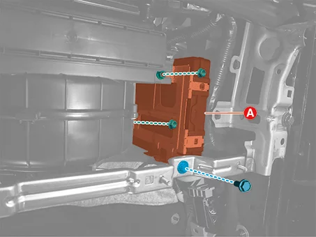
Remove the Integrated Body Control Unit (IBU) (A) after removing the bolt and nuts.
|
| 3. |
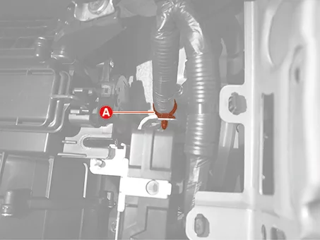
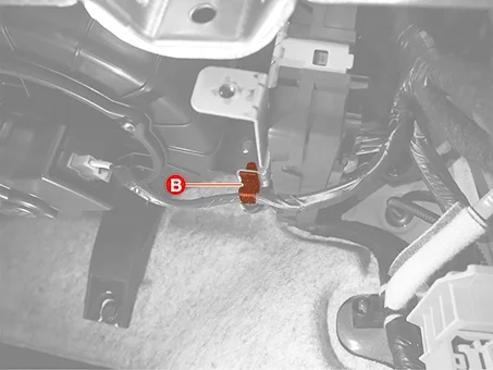
Remove the wiring clips (A), (B).
|
| 4. |
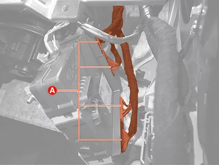
Disconnect the Integrated Body Control Unit (IBU) connectors (A).
|
| Installation |
| 1. |
Install in reverse order of removal.
|
| 2. |
Perform the order below with the KDS when replacing the Integrated Body Control Unit (IBU).
(S/W Management → Integrated Body Control Unit-BCM → Variant Coding)
(S/W Management → Integrated Body Control Unit-SMK → Smart Key Code Saving)
(S/W Management → Integrated Body Control Unit-TPMS → Vehicle Name Writing)
(S/W Management → Integrated Body Control Unit-TPMS → Wheel Sensor ID Writing)
(S/W Management → Identity Authentication Unit → Learning Mode)
|

