
Kia Seltos: Body Electrical System / Lighting System
Contents:
- Specification
- On Vehicle Inspection
- Back-up Lamp Removal and Installation
- Back-up Lamp Replacement
- Fog Lamp Removal and Installation
- Fog Lamp Replacement
- Fog Lamp Adjustment
- Hazard Switch Removal and Installation
- Headlamps Terminal Function
- Headlamps Removal and Installation
- Headlamps Replacement
- Headlamps Adjustment
- High Mounted Stop Lamp Removal and Installation
- License Lamp Removal and Installation
- License Lamp Replacement
- Luggage Lamp Removal and Installation
- Luggage Lamp Replacement
- Mood Lamp Removal and Installation
- Overhead Console Lamp Terminal Function
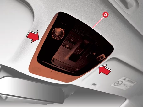
- Overhead Console Lamp Removal and Installation
- Overhead Console Lamp Inspection
- Rear Combination Lamp Terminal Function
- Rear Combination Lamp Removal and Installation
- Rear Combination Lamp Replacement
- Rheostat Removal and Installation
- Room Lamp Removal and Installation
- Room Lamp Replacement
- Side Mark Lamp Removal and Installation
- Side Mark Lamp Replacement
- Turn Signal Lamp Removal and Installation
- Turn Signal Lamp Replacement
- Vanity Lamp Removal and Installation
- Vanity Lamp Replacement
Specification
| Specification |
| Item |
Type |
Watt (W) |
|||
| Front |
Headlamps |
Standard type |
Low beam/High beam |
HB3 |
60 |
|
Turn signal lamp |
PY21W |
21 |
|||
|
Position/DRL |
LED |
- |
|||
| Option type |
Low beam/High beam (Sub) |
LED |
- |
||
|
High beam |
LED |
- |
|||
|
Turn signal lamp |
LED |
- |
|||
|
Position/DRL |
LED |
- |
|||
| Front auxiliary lamp (Position) |
LED |
- |
|||
| Fog lamp |
HB4 |
55 |
|||
|
LED |
- |
||||
| Rear |
Rear combination lamp |
Standard type |
Stop/Tail lamp |
P21/5W |
21 |
|
Turn signal lamp |
PY21W |
21 |
|||
| Option type |
Stop/Tail lamp |
LED |
- |
||
|
Turn signal lamp |
PY21W |
21 |
|||
| Back-up lamp |
W16W |
16 |
|||
| Fog lamp |
PY21W |
21 |
|||
| High mounted stop lamp |
LED |
- |
|||
| License lamp |
W5W |
5 |
|||
| Interior |
Overhead console lamp |
Standard type |
W10W |
10 |
|
| Option type |
LED |
- |
|||
| Room lamp |
Standard type |
FESTOON |
10 |
||
| Option type |
LED |
- |
|||
| Vanity lamp |
FESTOON |
5 |
|||
| Luggage lamp |
FESTOON |
10 |
|||
On Vehicle Inspection
| On Vehicle Inspection |
| Diagnosis with KDS |
| 1. |
The lighting system can be more quickly diagnosed for problems with the KDS (Refer to "DTC guide").
|
Back-up Lamp Removal and Installation
| Removal |
| 1. |
Remove the rear bumper assembly.
(Refer to Body - "Rear Bumper Assembly")
|
| 2. |
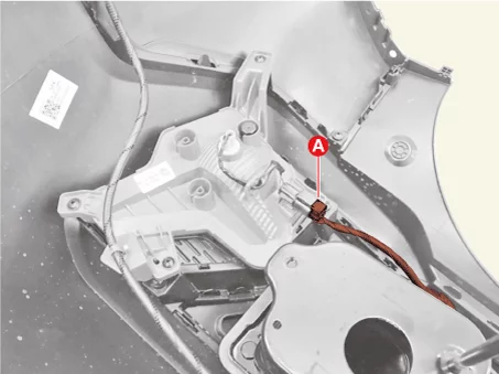
Disconnect the back-up lamp connectors (A).
|
| 3. |
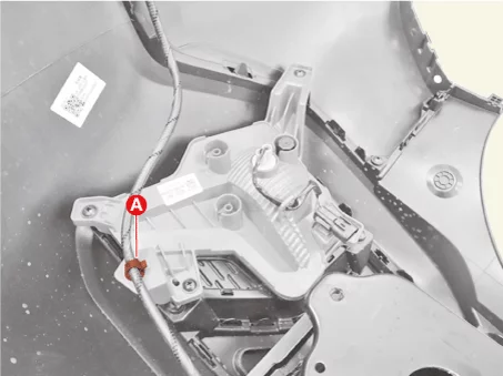
Remove the wiring clip (A) by using the remover.
|
| 4. |
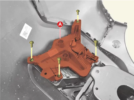
Remove the back-up lamp (A) after removing the screws.
|
| Installation |
| 1. |
Install in reverse order of removal.
|
Back-up Lamp Replacement
| Replacement |
| Bulb |
| [Back-up Lamp] |
| 1. |
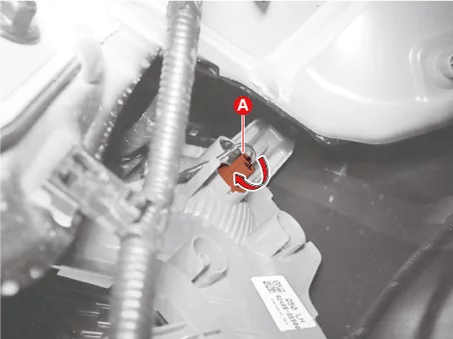
Remove the back-up lamp bulb socket (A) by turning in the counterclockwise.
|
| 2. |
Replace the back-up lamp bulb (A).
|
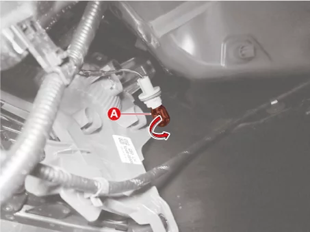
| 3. |
Install in reverse order of removal.
|
Fog Lamp Removal and Installation
| Removal |
| 1. |
Remove the front bumper.
(Refer to Body - "Front Bumper Assembly")
|
| 2. |
Remove the front fog lamp assembly (A) after removing the screws.
|
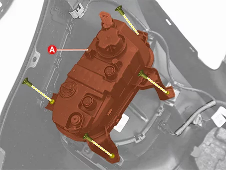
| Installation |
| 1. |
Install in reverse order of removal.
|
Fog Lamp Replacement
| Replacement |
| 1. |
Remove the front bumper.
(Refer to Body - "Front Bumper Assembly")
|
| 2. |
Remove the dust cap (A) by turning in the counterclockwise direction.
|
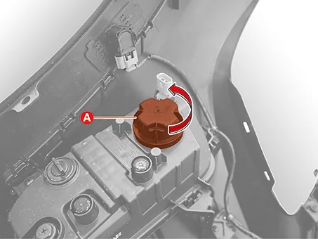
| 3. |
Remove the absorbent bracket (A) after removing the screws.
|
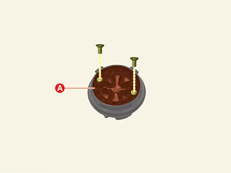
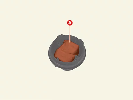
| 4. |
Replace the absorbent (A).
|

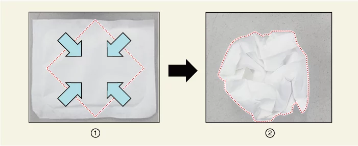
| 5. |
Install in reverse order of removal.
|
Fog Lamp Adjustment
| Adjustment |
| 1. |
Inflate the tires to the specified pressure and remove any loads from the vehicle except the driver,
spare tire, and tools.
|
| 2. |
The vehicle should be placed on a flat floor.
|
| 3. |
Check if there is something wrong with the suspension spring.
|
| 4. |
Clean the headlamp lens.
|
| 5. |
Draw vertical lines (Vertical lines passing through respective fog lamps centers) and a horizontal line
(Horizontal line passing through center of fog lamps) on the screen.
|
| 6. |
With the fog lamp and battery in normal condition, aim the fog lamp so the brightest portion falls on the
vertical lines.
|
| [Standard Type] |
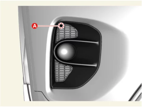
A : Adjustment bolt
|
| [Option Type] |
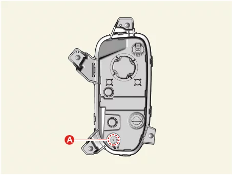
A : Adjustment bolt
|
| [Standard Type] |
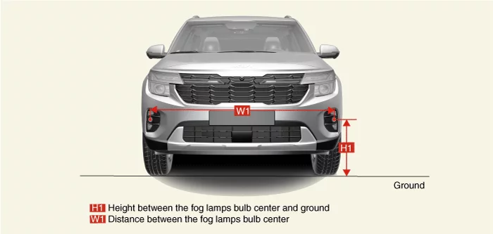
| Vehicle Condition |
H1 |
W1 |
Dimension |
| Empty |
500 (19.69) |
1,547 (60.91) |
mm (in.) |
| 1 person on-board |
495 (19.49) |
| Vehicle Condition |
H1 |
W1 |
Dimension |
| Empty |
506 (19.92) |
1,547 (60.91) |
mm (in.) |
| 1 person on-board |
501 (19.72) |
| [Option Type] |
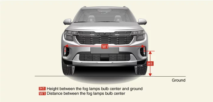
| Vehicle Condition |
H1 |
W1 |
Dimension |
| Empty |
480 (18.90) |
1,554 (61.18) |
mm (in.) |
| 1 person on-board |
475 (18.70) |
| Vehicle Condition |
H1 |
W1 |
Dimension |
| Empty |
486 (19.13) |
1,554 (61.18) |
mm (in.) |
| 1 person on-board |
481 (18.94) |
| 1. |
Turn the front fog lamp on without the driver aboard.
|
| 2. |
The cut-off line should be projected in the allowable range (shaded region).
|
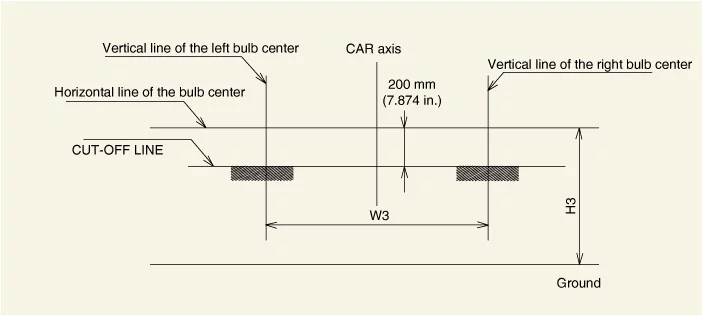
Hazard Switch Removal and Installation
| Removal |
| 1. |
Remove the crash pad center air vent.
(Refer to Body - "Crash Pad Air Vent")
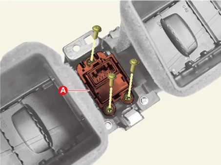
|
| 2. |
Remove the hazard switch (A) after removing the screws.
|
| Installation |
| 1. |
Install in reverse order of removal.
|
Headlamps Terminal Function
| Connector and Terminal Function |
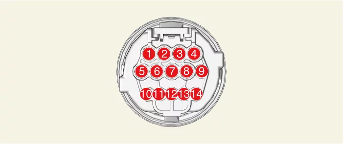
| Terminal |
Function |
|
|
Standard Type |
Option Type |
|
|
1 |
Low beam / high beam ( + ) |
Low beam ( + ) LED |
|
2 |
- |
High beam ( + ) LED |
|
3 |
Turn signal lamp ( + ) |
Turn signal lamp ( + ) LED |
|
4 |
- |
Battery ( + ) |
|
5 |
Low beam / high beam ground ( - ) |
- |
|
6 |
Leveling device ground ( - ) |
Leveling device ground ( - ) |
|
7 |
DRL / position lamp ground ( - ) |
- |
|
8 |
Turn signal lamp ground ( - ) |
Battery ( - ) |
|
9 |
Position lamp ( + ) |
Position lamp ( + ) LED |
|
10 |
DRL ( + ) |
DRL ( + ) LED |
|
11 |
Leveling device ( - ) |
Leveling device ground ( + ) |
|
12 |
Leveling device signal |
Leveling device signal |
|
13 |
DC motor ( + ) |
Low beam tell-tail |
|
14 |
DC motor ground ( - ) |
Turn signal lamp tell-tail |
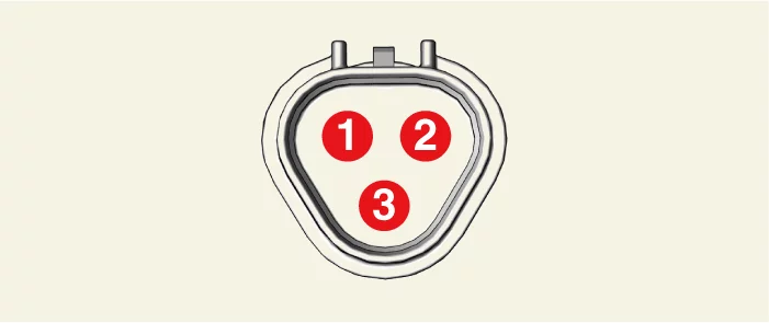
| Terminal |
Fuction |
|
1 |
Position lamp ( + ) RH |
|
2 |
Position lamp ( + ) LH |
|
3 |
Ground ( - ) |
Headlamps Removal and Installation
| Removal |
| 1. |
Remove the front bumper assembly.
(Refer to Body - "Front Bumper Assembly")
|
| 2. |
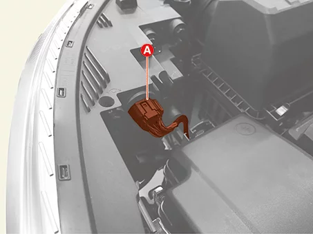
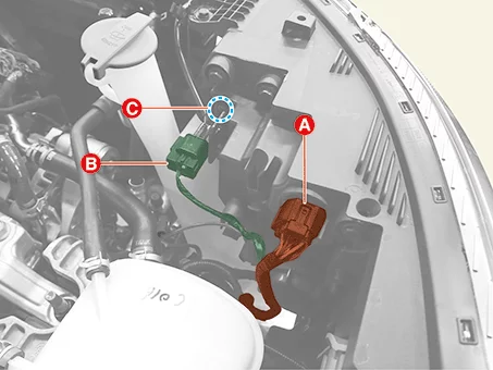
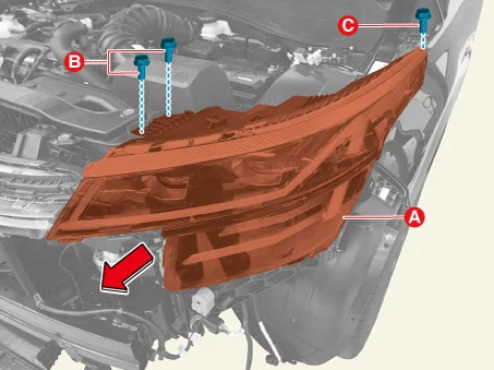
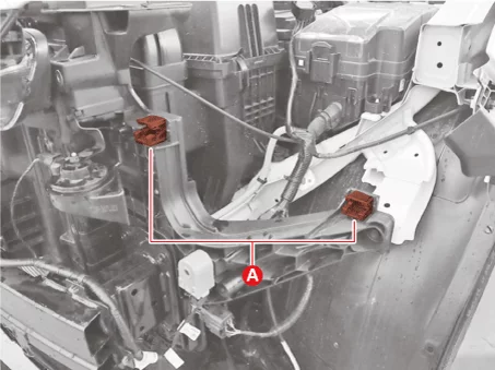
Disconnect the headlamp connector.
[Driver's side]
Disconnect the headlamp connector (A).
[Passenger's side]
Disconnect the headlamp connector (A), connector (B) and remove the wiring clip (C).
|
| 3. |
Remove the headlamp (A) in the direction of the arrow after removing the bolts.
|

| 1. |
Remove the radiator grille upper garnish.
(Refer to Body - "Front Bumper Assembly")
|
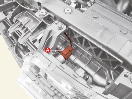
| 2. |
Disconnect the front auxiliary lamp connector (A).
|
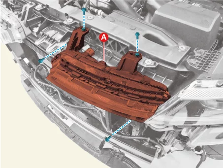
| 3. |
Remove the front auxiliary lamp (A) after removing the bolts.
|
| Installation |
| 1. |
Install in reverse order of removal.
|
Headlamps Replacement
| Replacement |
| [Low Beam / High Beam] |
| 1. |
Disconnect the negative ( - ) battery terminal.
|
| 2. |
Remove the headlamps.
(Refer to Lighting System - "Headlamps")
|
| 3. |
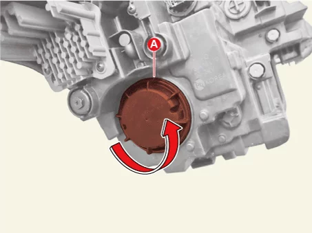
Remove the dust cap (A) by turning in the counterclockwise direction.
|
| 4. |
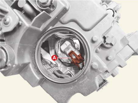
Disconnect the low beam / high beam connector (A).
|
| 5. |
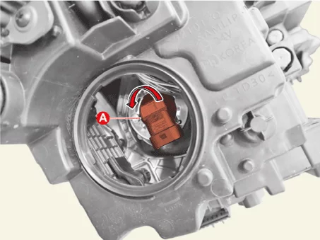
Remove the low beam / high beam bulb socket by turning in the counterclockwise direction.
|
| 6. |
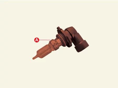
Replace the low beam / high beam bulb (A).
|
| 7. |
Install in reverse order of removal.
|
| [Turn Signal Lamp] |
| 1. |
Disconnect the negative ( - ) battery terminal.
|
| 2. |
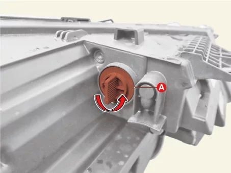
Remove the turn signal lamp bulb socket (A) by turning in the counterclockwise direction.
|
| 3. |
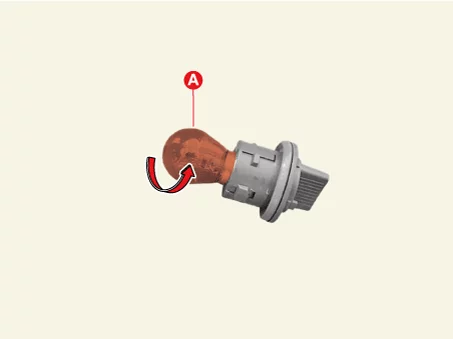
Replace the turn signal lamp bulb (A).
|
| 4. |
Install in reverse order of removal.
|
| [Headlamp] |
| 1. |
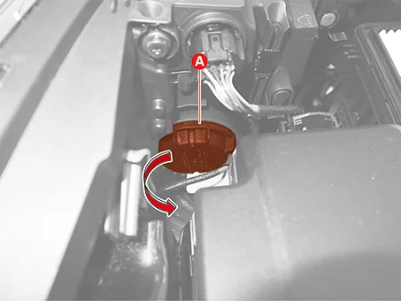
Remove the dust cap (A) by turning in the counterclockwise direction.
|
| 2. |
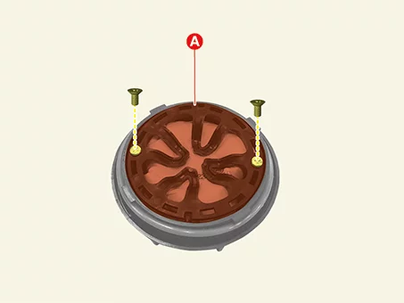
Remove the absorbent bracket (A) after removing the screws.
|
| 3. |
Replace the absorbent (A).
|
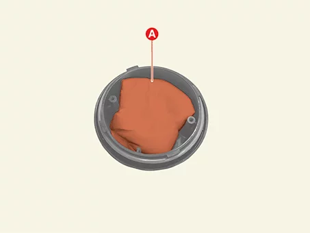
| 4. |
Install in reverse order of removal.
|
| [Front Auxiliary Lamp] |
| 1. |
Remove the dust cap (A) by turning in the counterclockwise direction.
|
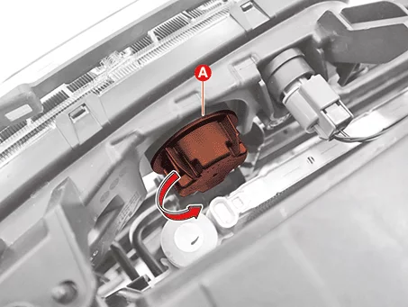
| 2. |
Remove the absorbent bracket (A) after removing the screws.
|
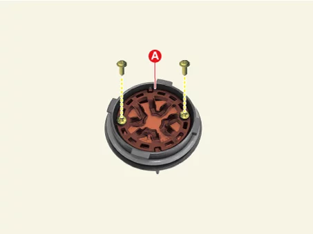
| 3. |
Replace the absorbent (A).
|
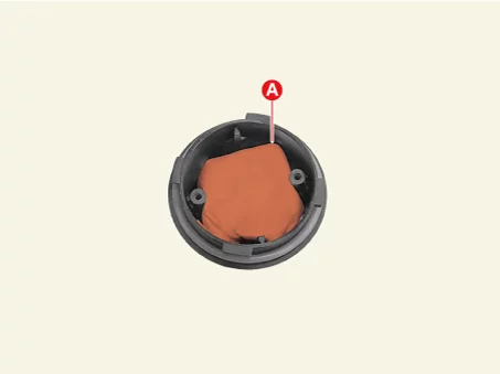
| 4. |
Install in reverse order of removal.
|
Headlamps Adjustment
| Adjustment |
| 1. |
Inflate the tires to the specified pressure and remove any loads from the vehicle except the driver,
spare tire, and tools.
|
| 2. |
The vehicle should be placed on a flat floor.
|
| 3. |
Check if there is something wrong with the suspension spring.
|
| 4. |
Clean the headlamp lens.
|
| 5. |
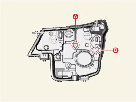
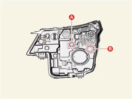
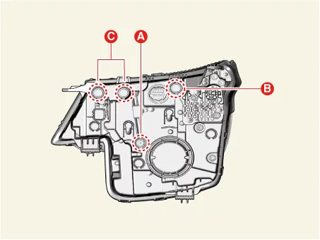
Draw vertical lines (Vertical lines passing through respective headlamp centers) and a horizontal line
(Horizontal line passing through center of headlamps) on the screen.
|
| 6. |
With the headlamp and battery in normal condition, aim the headlamps so the brightest portion falls on
the horizontal and vertical lines.
[Standard Type]
[Option 1 Type]
[Option 2 Type]
|
| [Standard / Option 1 Type] |
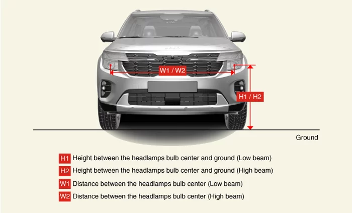
| Vehicle Condition |
H1 |
H2 |
W1 |
W2 |
Dimension |
| Empty |
757 (29.80) |
757 (29.80) |
1,438 (56.61) |
1,438 (56.61) |
mm (in.) |
| 1 person on-board |
752 (29.60) |
752 (29.60) |
| Vehicle Condition |
H1 |
H2 |
W1 |
W2 |
Dimension |
| Empty |
763 (30.04) |
763 (30.04) |
1,438 (56.61) |
1,438 (56.61) |
mm (in.) |
| 1 person on-board |
758 (29.84) |
758 (29.84) |
| [Option 2 Type] |
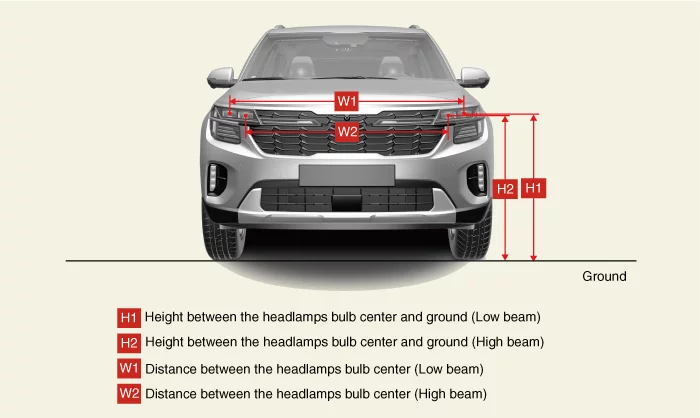
| Vehicle Condition |
H1 |
H2 |
W1 |
W2 |
Dimension |
| Empty |
854(33.62) |
844 (33.23) |
1,373 (54.06) |
1,169 (46.02) |
imm (in.) |
| 1 person on-board |
849 (33.42) |
839 (33.03) |
| Vehicle Condition |
H1 |
H2 |
W1 |
W2 |
Remark |
| Empty |
860 (33.86) |
850 (33.46) |
1,373 (54.06) |
1,169 (46.02) |
mm (in.) |
| 1 person on-board |
855 (33.66) |
845 (33.27) |
| [Low Beam] |
| 1. |
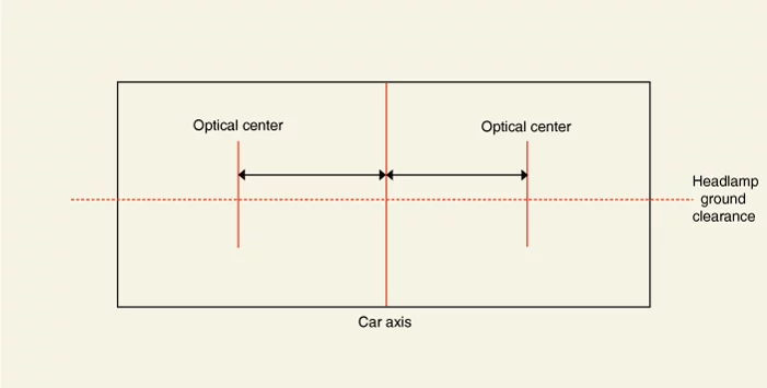
VOR Type (Visually Optically aimed using the Right side of the low beam) :Draw a horizontal line at -0.2%
from the headlamp ground clearance.
|
| 2. |
Turn on to low beam the check the up-down/left-right aiming position.
|
| 3. |
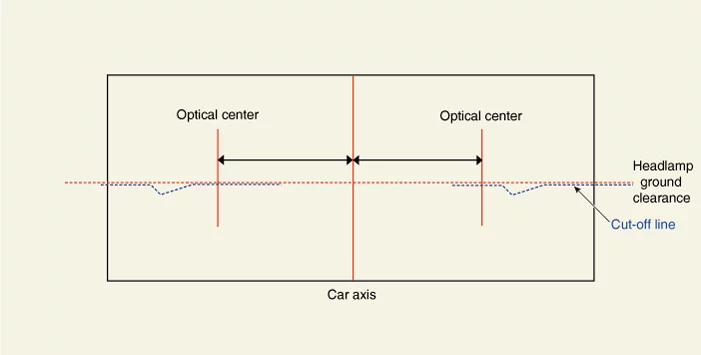
Up-down Aiming : Match the cut-off line -0.2% line on the screen.
|
| 4. |
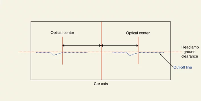
Left-Right Aiming : Match the left-right aiming point to the vertical line of optical center on the
screen.
|
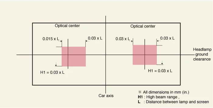
| [High Beam ] |
| 1. |
High beam hot point must be checked after low beam aiming. (No in-line aiming)
|
| 2. |
If high beam hot point deviates from below hot zone (RED BOX) after low beam aiming, this is because of
defective lamps or damage and it should be inspected further or replace as needed.
|
High Mounted Stop Lamp Removal and Installation
| Removal |
| 1. |
Remove the rear spoiler.
(Refer to Body - "Rear Spoiler")
|
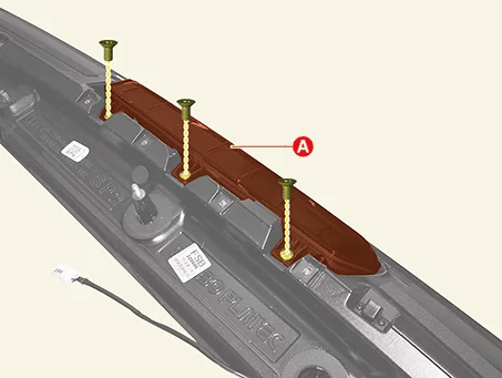
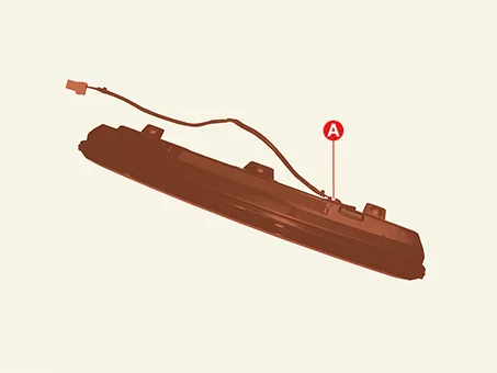
| 2. |
Remove the high mounted stop lamp (A) after removing the screws.
|
| Installation |
| 1. |
Install in reverse order of removal.
|
License Lamp Removal and Installation
| Removal |
| 1. |
Remove the tailgate outside handle.
(Refer to Body - "Tailgate Outside Handle")
|
| Installation |
| 1. |
Install in reverse order of removal.
|
License Lamp Replacement
| Replacement |
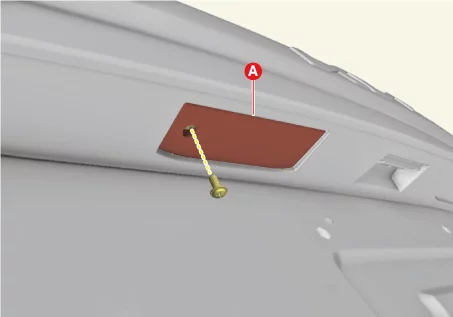
| 1. |
Remove the license lamp lens (A) after removing the screw.
|
| 2. |
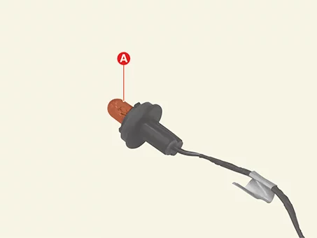
Replace the license lamp bulb (A).
|
| 3. |
Install in reverse order of removal.
|
Luggage Lamp Removal and Installation
| Removal |
| 1. |
Disconnect the negative ( - ) battery terminal.
|
| 2. |
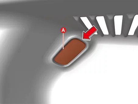
Remove the luggage lamp (A) by using the remover.
|
| 3. |
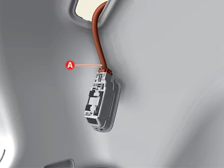
Disconnect the luggage lamp connector (A).
|
| Installation |
| 1. |
Install in reverse order of removal.
|
Luggage Lamp Replacement
| Replacement |
| 1. |
Remove the luggage lamp.
(Refer to Lighting System - "Luggage Lamp")
|
| 2. |
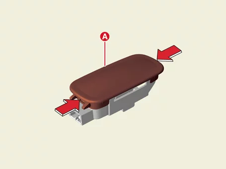
Remove the luggage lamp lens (A) by pushing the hook in the direction of the arrow.
|
| 3. |
Replace the luggage lamp bulb (A).
|
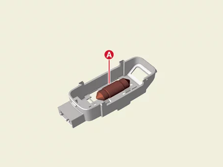
| 4. |
Install in reverse order of removal.
|
Mood Lamp Removal and Installation
| Removal |
| 1. |
Remove the crash pad center panel.
(Refer to Body - "Crash Pad Lower Panel")
|
| 2. |
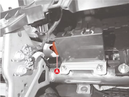
Disconnect the mood lamp unit connector (A).
|
| 3. |
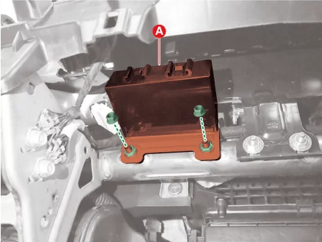
Remove the mood lamp unit (A) after removing the nuts.
|
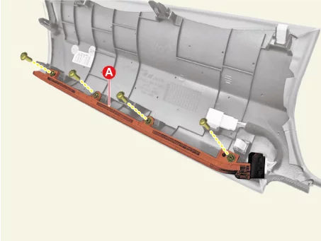
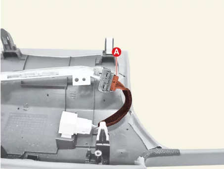
| Crash Pad Garnish |
| 1. |
Remove the crash pad garnish [Passenger's side].
(Refer to Body - "Crash Pad Lower Panel")
|
| 2. |
Remove the mood lamp.
|
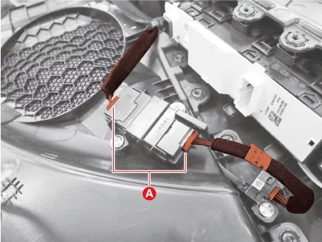
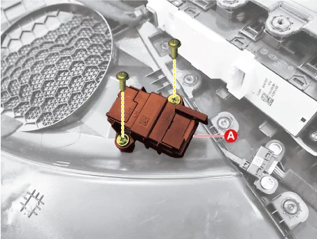
| Front Door Trim |
| 1. |
Remove the front door trim.
(Refer to Body - "Front Door Trim")
|
| 2. |
Remove the mood lamp.
|
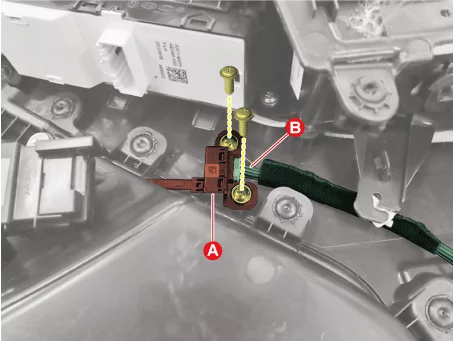
| 1. |
Remove the front door trim.
(Refer to Body - "Front Door Trim")
|
| 2. |
Remove the mood lamp.
|
| Installation |
| 1. |
Install in reverse order of removal.
|
Overhead Console Lamp Terminal Function
| Connector and Terminal Function |
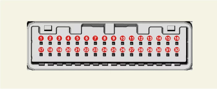
| [A Type] |
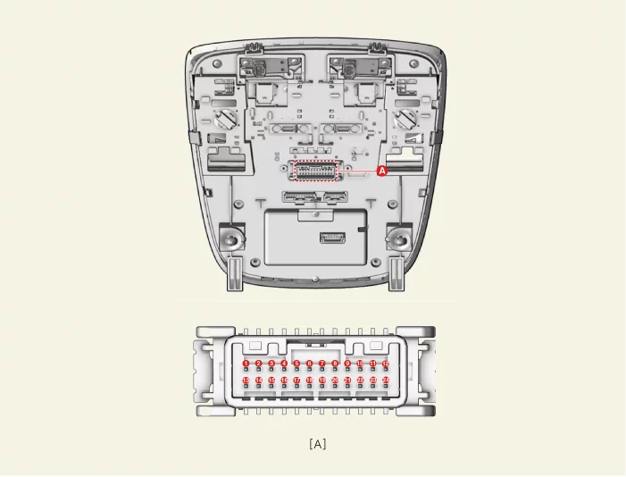
| Connector A |
|||
|
Terminal |
Function |
Terminal |
Function |
|
1 |
Battery (+) |
13 |
- |
|
2 |
Airbag warning lamp |
14 |
- |
|
3 |
Illumination ( - ) |
15 |
- |
|
4 |
- |
16 |
- |
|
5 |
Built-in cam IND |
17 |
- |
|
6 |
- |
18 |
Room lamp signal |
|
7 |
MTS keypad signal |
19 |
Room lamp signal (Output) |
|
8 |
IG 1 |
20 |
- |
|
9 |
Ground |
21 |
- |
|
10 |
Built-in cam signal |
22 |
- |
|
11 |
PAB off IND |
23 |
- |
|
12 |
Ground |
24 |
- |
| [B Type] |
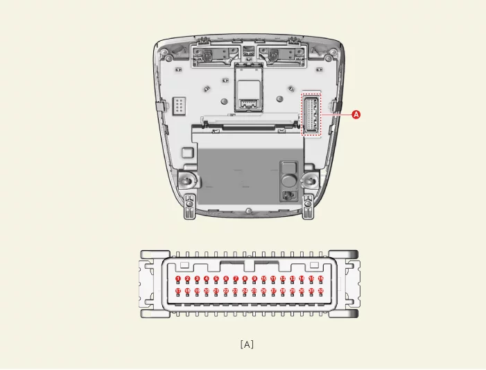
| Connector A |
|||
|
Terminal |
Function |
Terminal |
Function |
|
1 |
Battery (+) |
17 |
- |
|
2 |
Airbag warning lamp |
18 |
- |
|
3 |
Illumination ( - ) |
19 |
- |
|
4 |
- |
20 |
- |
|
5 |
Built-in cam IND |
21 |
- |
|
6 |
- |
22 |
Room lamp signal |
|
7 |
MTS keypad signal |
23 |
- |
|
8 |
IG 1 |
24 |
- |
|
9 |
Ground |
25 |
- |
|
10 |
Built-in cam signal |
26 |
- |
|
11 |
- |
27 |
- |
|
12 |
- |
28 |
- |
|
13 |
Ground |
29 |
- |
|
14 |
- |
30 |
- |
|
15 |
PAB off IND |
31 |
- |
|
16 |
Door signal |
32 |
- |
Overhead Console Lamp Removal and Installation
| Removal |
| 1. |
Disconnect the negative ( - ) battery terminal.
|
| 2. |
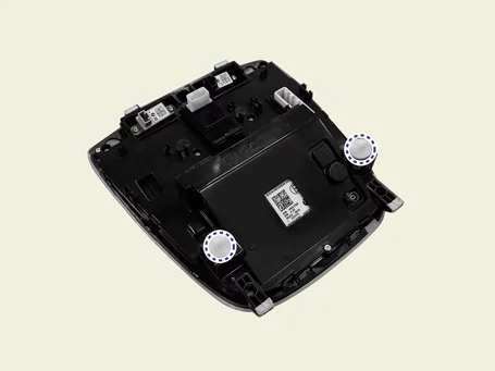
Remove the overhead console lamp (A) by using the remover.
|
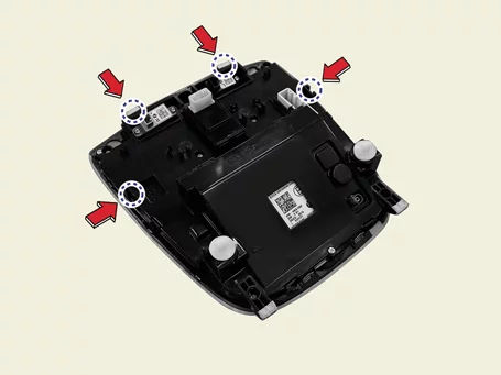

| 3. |
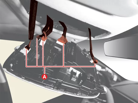
Disconnect the overhead console lamp connectors (A).
|
| Installation |
| 1. |
Install in reverse order of removal.
|
Overhead Console Lamp Inspection
| Inspection |
| 1. |
Remove the overhead console lamp.
(Refer to Lighting System - "Overhead Console Lamp")
|
| 2. |
Check for continuity between terminals.
|
Rear Combination Lamp Terminal Function
| Connector and Terminal Function |
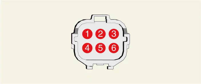
| Terminal |
Function |
|
|
Standard Type |
Option Type |
|
|
1 |
Tail lamp ( + ) |
Tail lamp ( + ) |
|
2 |
Stop lamp ( + ) |
Stop lamp ( + ) |
|
3 |
Turn signal lamp ( + ) |
Turn signal lamp ( + ) |
|
4 |
- |
Stop lamp ( + ) LED |
|
5 |
- |
Ground |
|
6 |
Ground |
- |
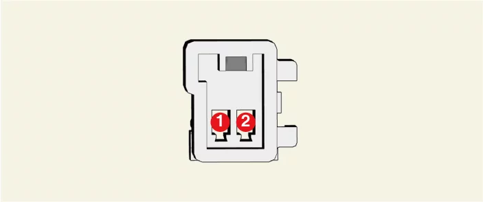
|
Terminal |
Function |
|
1 |
Ground |
|
2 |
Tail lamp ( + ) |
Rear Combination Lamp Removal and Installation
| Removal |
| [Outside Rear Combination Lamp] |
| 1. |
Disconnect the negative ( - ) battery terminal.
|
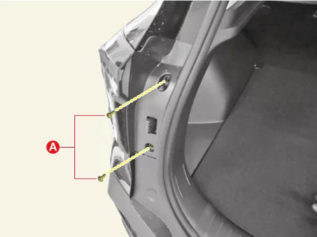
| 2. |
Remove the mounting screws (A).
|
| 3. |
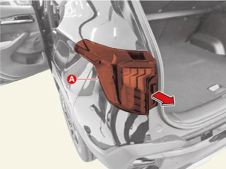
Remove the outside rear combination lamp (A) in the direction of the arrow.
|
| 4. |
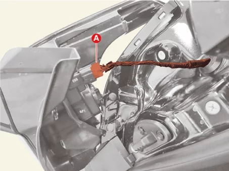
Disconnect the outside rear combination lamp connector (A).
|
| [Inside Rear Combination Lamp] |
| 1. |
Disconnect the negative ( - ) battery terminal.
|
| 2. |
Remove the tailgate lid lower trim.
(Refer to Body - " Tailgate Lid Trim")
|
| 3. |
Disconnect both inside rear combination lamp connectors (A).
|
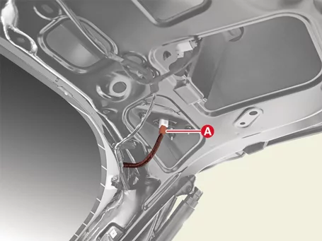
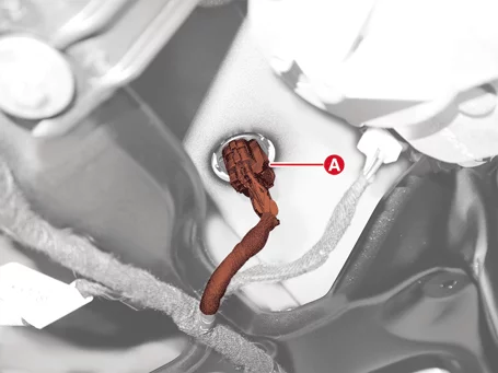
| 4. |
Disconnect the license lamp connector (A).
|
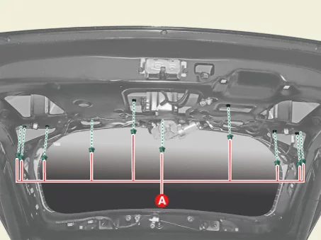
| 5. |
Remove the nuts (A).
|
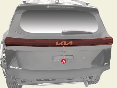
| 6. |
Remove the inside rear combination lamp (A).
|
| Installation |
| 1. |
Install in reverse order of removal.
|
Rear Combination Lamp Replacement
| Replacement |
| [Turn Signal Lamp] |
| 1. |
Remove the outside rear combination lamp.
(Refer to Lighting System - "Rear Combination Lamp")
|
| 2. |
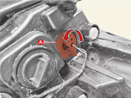
Remove the turn signal lamp bulb socket (A) by turning in the counterclockwise.
|
| 3. |
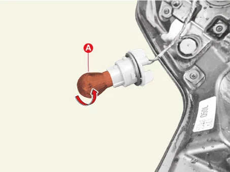
Remove the turn signal lamp bulb (A) by turning in the counterclockwise.
|
| 4. |
Install in reverse order of removal.
|
| [Tail/Stop Lamp] |
| 1. |
Remove the outside rear combination lamp.
(Refer to Lighting System - "Rear Combination Lamp")
|
| 2. |
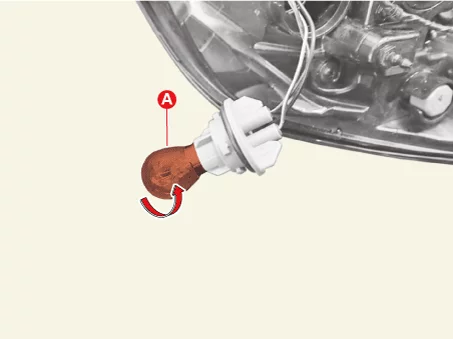
Remove the tail/stop lamp bulb socket (A) by turning in the counterclockwise.
|
| 3. |
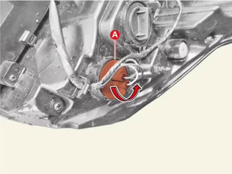
Remove the tail/stop lamp bulb by turning in the counterclockwise.
|
| Absorbent |
| 1. |
Remove the outside rear combination lamp.
(Refer to Lighting System - "Rear Combination Lamp")
|
| 2. |
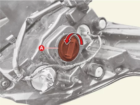
Remove the dust cap (A) by turning in the counterclockwise.
|
| 3. |
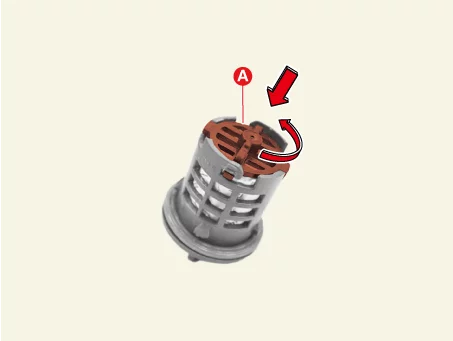
Remove the cover (A) by pressing it in the direction of the arrow and then turning it counterclockwise.
|
| 4. |
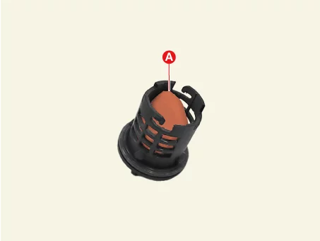
Replace the absorbent (A).
|
| 5. |
Install in reverse order of removal.
|
Rheostat Removal and Installation
| Removal |
| 1. |
Remove the crash pad lower panel.
(Refer to Body - "Crash Pad Lower Panel")
|
| 2. |
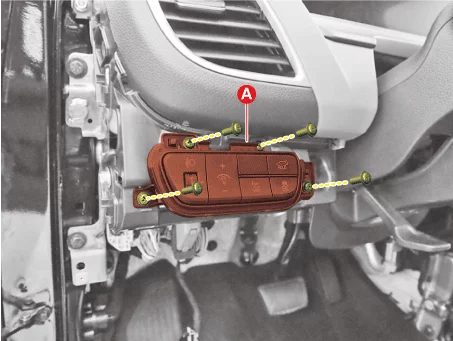
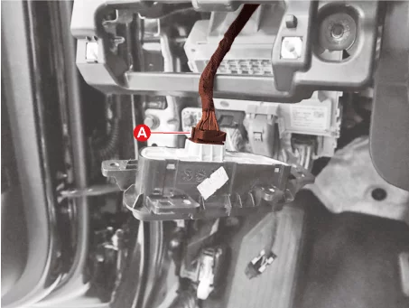
Remove the crash pad side switch (A) after removing the screws.
|
| 3. |
Disconnect the crash pad side switch connector (A).
|
| Installation |
| 1. |
Install in reverse order of removal.
|
Room Lamp Removal and Installation
| Removal |
| 1. |
Disconnect the negative ( - ) battery terminal.
|
| 2. |
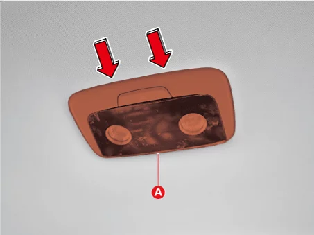
Remove the room lamp(A) by using the remover.
|
| 3. |
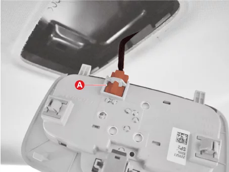
Disconnect the room lamp connector (A).
|
| Installation |
| 1. |
Install in reverse order of removal.
|
Room Lamp Replacement
| Replacement |
| 1. |
Disconnect the negative ( - ) battery terminal.
|
| 2. |
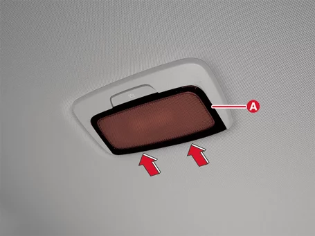
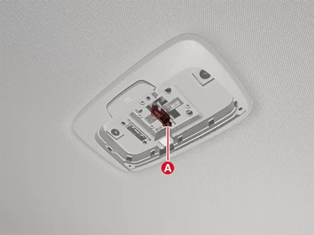
Remove the room lamp cover (A) by using the remover.
|
| 3. |
Replace the room lamp bulb (A).
|
| 4. |
Install in reverse order of removal.
|
Side Mark Lamp Removal and Installation
| Removal |
| 1. |
Remove the front bumper assembly.
(Refer to Body - "Front Bumper Assembly")
|
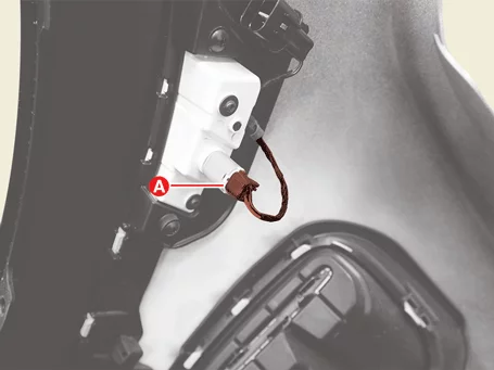
| 2. |
Disconnect the side mark lamp connector (A).
|
| 3. |
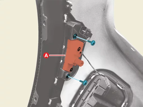
Remove the side mark lamp (A) after removing the screws.
|
| Installation |
| 1. |
Install in reverse order of removal.
|
Side Mark Lamp Replacement
| Replacement |
| 1. |
Remove the front bumper assembly.
(Refer to Body - "Front Bumper Assembly")
|
| 2. |
Disconnect the side mark lamp connector (A).
|
| 3. |
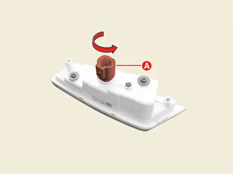
Remove the side mark lamp socket (A).
|
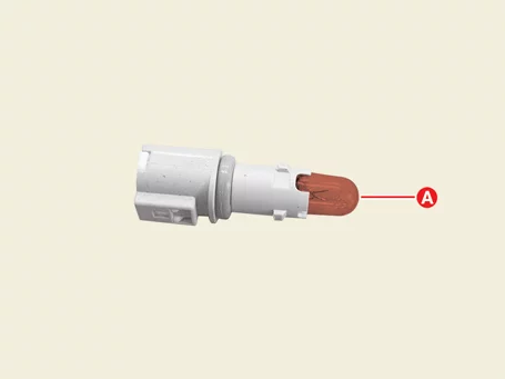
| 4. |
Replace the side mark lamp bulb (A).
|
Turn Signal Lamp Removal and Installation
| Removal |
| 1. |
Disconnect the battery negative ( - ) terminal.
|
| 2. |
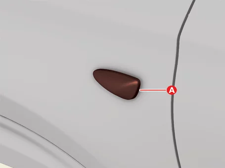
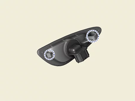
Remove the side repeater lamp (A) by pressing the hook in the direction of the arrow.
|
| 3. |
Disconnect the side repeater lamp connector (A).
|
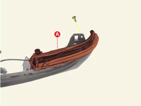
| 1. |
Remove the outside view mirror lower scalp.
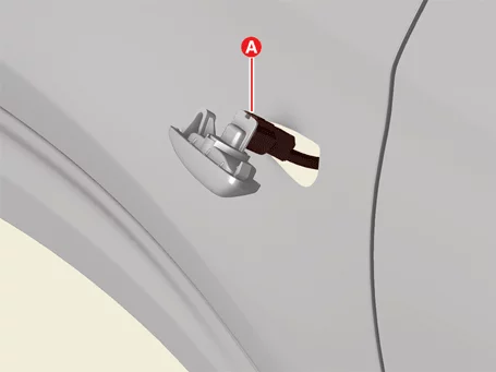
(Refer to Body - "Outside Rear View Mirror")
|
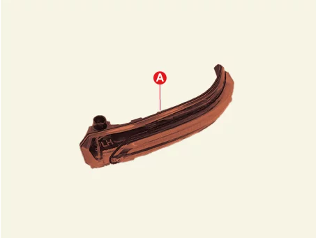
| 2. |
Remove the turn signal lamp (A) after removing the screw.
|
| Installation |
| 1. |
Install in reverse order of removal.
|
Turn Signal Lamp Replacement
| Replacement |
| 1. |
Remove the side repeater lamp [Fender].
(Refer to Lighting System - "Trun Signal Lamp")
|
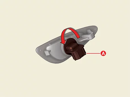
| 2. |
Replace the bulb (A).
|
Vanity Lamp Removal and Installation
| Removal |
| 1. |
Disconnect the negative ( - ) battery terminal.
|
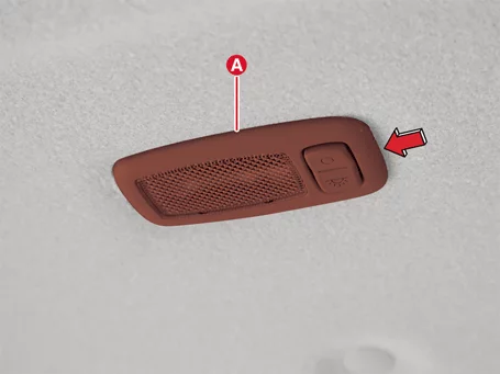
| 2. |
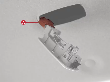
Remove the vanity lamp (A) by using the remover.
|
| 3. |
Disconnect the vanity lamp connector (A).
|
| Installation |
| 1. |
Install in reverse order of removal.
|
Vanity Lamp Replacement
| Replacement |
| Bulb |
| 1. |
Disconnect the negative ( - ) battery terminal.
|
| 2. |
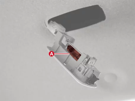
Remove the vanity lamp (A) by using the remover.
|
| 3. |
Replace the vanity lamp bulb (A).
|
| 4. |
Install in reverse order of removal.
|


Other information:
Kia Seltos SP2 (2021-2026) Service Manual: General Safety Information and Caution
Precaution (R-134a) When Handling Refrigerant 1. R-134a liquid refrigerant is highly volatile. A drop on the skin of your hand could result in localized frostbite. When handling the refrigerant, be sure to wear gloves. 2. It is standard practice to wear goggles or glasses to protect your eyes, and gloves to protect your hands.