
Kia Seltos SP2 (2021-2026) Service Manual / Maintenance / Chassis
Kia Seltos: Maintenance / Chassis
Contents:
- Brake/Clutch Fluid Inspection
- Brake Lines, Hoses and Connections Inspection
- Disc Brakes and Pads Inspection
- Drive Shafts and Boots Inspection
- Parking Brake Inspection
- Steering Gear Rack, Linkage and Boots Inspection
- Suspension Ball Joints Inspection
- Suspension Mounting Bolts Inspection
- Tire (pressure & tread wear) Inspection
- Rear Differential Carrier Oil Lubricant
- Rear Differential Carrier Oil Inspection
- Rear Differential Carrier Oil Replacement
- Transfer Oil Lubricant
- Transfer Oil Inspection
- Transfer Oil Replacement
Brake/Clutch Fluid Inspection
| Inspection |
Check the brake fluid level in the brake fluid reservoir. The level should be between “MIN” and “MAX” marks on
the side of the reservoir.
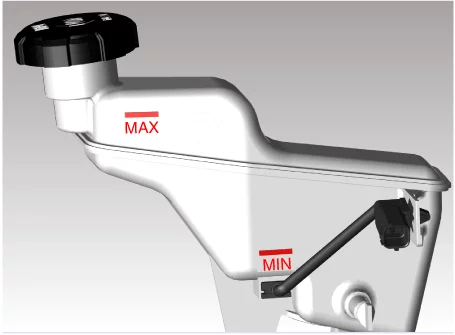
Use only hydraulic brake fluid conforming to DOT 4 specification.
Check the brake system for any leakage if the fluid level is extremely low (lower than MIN).
(Refer to Brake System - "Inspection")
Brake Lines, Hoses and Connections Inspection
| Inspection |
Visually check for proper installation, chafing, cracks, deterioration and any leakage.
Replace any deteriorated or damaged parts immediately.
Disc Brakes and Pads Inspection
| On Vehicle Inspection |
Disc Cleaning before Inspection
The rust caused by leaving the vehicle unattended for a long period of time is naturally removed under normal
driving conditions. It may affect thickness and runout measurements, please remove rust on the brake disc for
accurate measurements.
| 1. |
Check the brake disc for rust.
|
| 2. |
Spray the cleaning solution on rusted surface of disc.
|

| 3. |
Drive the vehicle up to 30 MPH and depress the brake up to stop for complete repeat more than 5 cycles.
|
| 4. |
Clean the brake disc with clean water.
|
| 5. |
Check the brake disc for rust.
|
| 6. |
If rust is not removed, repeat the above procedure again.
|
Front Brake Disc Thickness Check
| 1. |
Remove the front wheel and tires.
(Refer to Suspension System - "Wheel")
|
| 2. |
Check the brake disc for damage.
|
| 3. |
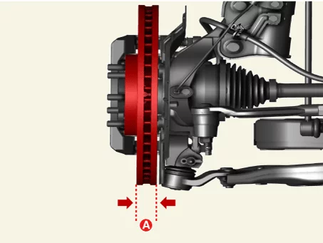
Measure the brake disc thickness (A) and run-out using the micro meter and dial gauge at least 24
locations on the same column along the lines shown in the figure below.
|
| 4. |
If the thickness difference between each measuring part is greater than standard, resurface or replace
the brake disc.
|

| 5. |
Install the front wheel and tires.
(Refer to Suspension System - "Wheel")
|
Front Brake Disc Runout Inspection
| 1. |
Remove the front wheel and tires.
(Refer to Suspension System - "Wheel")
|
| 2. |
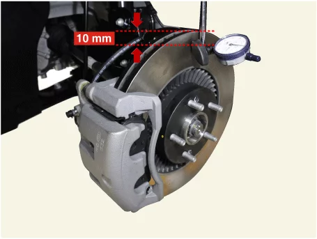
Install the dial gauge perpendicular to the brake disc's external diameter of 10 mm (0.40 in.) and rotate
the disc to measure the run-out.
|
| 3. |
If the brake disc run-out exceeds the limit, resurface or replace the brake disc.
|
| 4. |
Install the front wheel and tires.
(Refer to Suspension System - "Wheel")
|
Rear Brake Disc Thickness Check
| 1. |
Remove the rear wheel and tires.
(Refer to Suspension System - "Wheel")
|
| 2. |
Check the brake disc for damage.
|
| 3. |
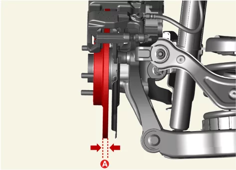
Measure the brake disc thickness (A) and run out using a micrometer and dial gauge. Measure it at least
24 points.
|
| 4. |
If the thickness difference between each measuring part is greater than standard, resurface or replace
the brake disc.
|
| 5. |
Install the rear wheel and tires.
(Refer to Suspension System - "Wheel")
|
Rear Brake Disc Runout Inspection
| 1. |
Remove the rear wheel and tires.
(Refer to Suspension System - "Wheel")
|
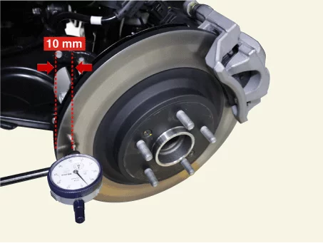
| 2. |
Install the dial gauge perpendicular to the brake disc's external diameter of 10 mm (0.40 in.) and rotate
the disc to measure the run-out.
|
| 3. |
If the brake disc run-out exceeds the limit, resurface or replace the brake disc.
|
| 4. |
Install the rear wheel and tires.
(Refer to Suspension System - "Wheel")
|
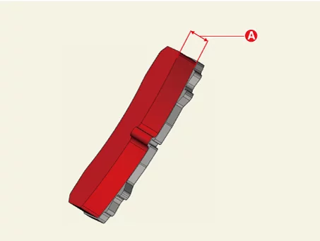
| Brake Pad Check |
| 1. |
Check brake pad thickness (A). If the thickness is thinner than the limit, replace the brake pads.
|
| 2. |
Check that grease is applied to sliding contact points and check the pad and backing metal for damage.
|
Drive Shafts and Boots Inspection
| Inspection |
| 1. |
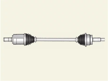
Check the drive shaft boots for loose clamps, cracks, grease leaks, kinks or damage.
|
Parking Brake Inspection
| Inspection |
| [Electric Parking Brake (EPB)] |
| 1. |
Check if the parking brake applying sound is heard when the EPB switch is operated.
|
| 2. |
Make sure that the parking brake indicator 'ON' when EPB switch applied and 'OFF' after EPB switch
released.
|
| [None EPB] |
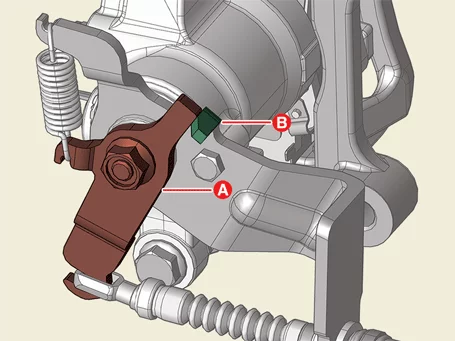
After disassembling/assembling the torque member or replacing the caliper, parking brake cable or brake
disc, re-adjust the parking brake.
|
| 1. |
To fit the cable, follow one of these procedures before adjusting.
|
| 2. |
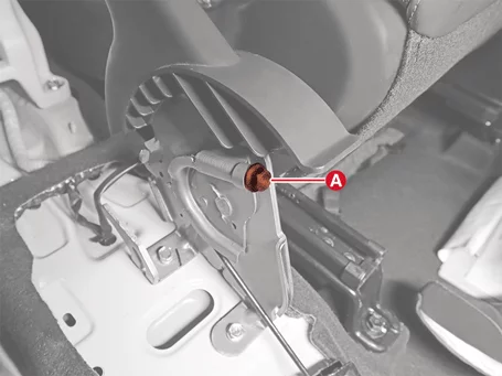
Remove the floor console assembly.
(Refer to Body - "Floor Console Assembly")
|
| 3. |
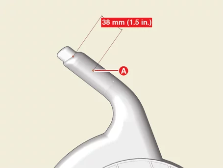
After fitting the cable, adjust the parking brake cable so that the stroke is 5 - 6 notch when operating
the pedal with 30kgf at point (A).
|
| 4. |
Make sure that there is no gap between adjustment nut and clip after adjusting the parking brake.
|
| 5. |
Make sure that the brakes are not drag.
|
| 6. |
Make sure that the parking brake switch is 'ON' before the parking lever is operated by 1 notch and 'OFF'
when released.
|
| 7. |
Check whether the wheel operates smoothly.
|
| 8. |
Perform driving test.
|
Steering Gear Rack, Linkage and Boots Inspection
| Inspection |
Steering Wheel Play Inspection
| 1. |
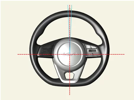
Align the steering wheel in a straight-ahead position using a digital level or other equivalent tools.
|
| 2. |
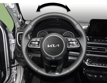
With MDPS power on, lightly turn the steering wheel from side to side to measure the distance the
steering wheel rotates until the wheel moves.
|
| 3. |
If the steering wheel play exceeds standard value, inspect the steering column, shaft, and linkages.
|
Checking Stationary Steering Effort
| 1. |
Align the steering wheel in a straight-ahead position using a digital level or other equivalent tools.
|
| 2. |
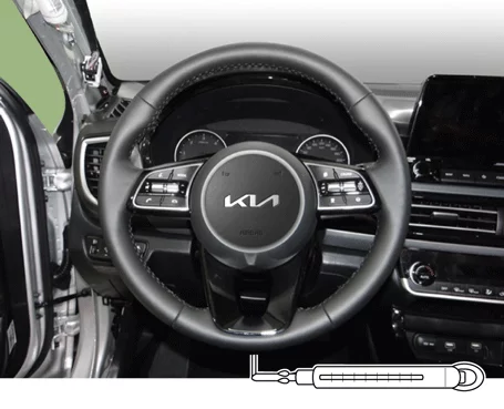
With MDPS powered on, apply a spring scale to the end of the steering wheel and pull the scale to measure
the force when the steering wheel begins to move.
|
| 3. |
If the measured value exceeds standard value, inspect the steering gear box or MDPS.
|
Steering Wheel Off Center Inspection
| 1. |
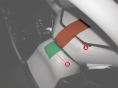
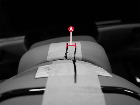
Mark the steering wheel upper (A) and upper cover (B) using the masking tape.
|
| 2. |
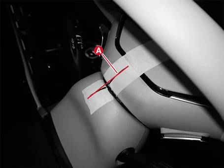
Align the steering wheel and mark the straight line (A) on the masking tape.
|
| 3. |
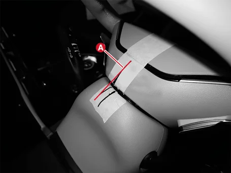
Keep the vehicle straight and drive about 100 m, and mark the new straight line (A) as the steering wheel
is turned.
|
| 4. |
Remove the front wheel and tires.
(Refer to Suspension System - "Wheel")
|
| 5. |
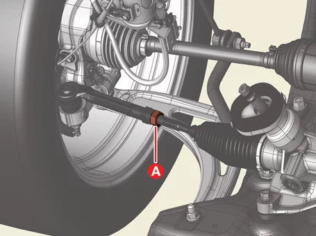
Loosen the tie rod end nut (A) enough to adjust the steering wheel off center.
|
| 6. |
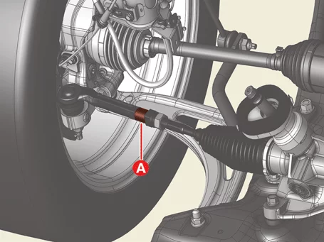
Fix the tie rod end (A) with a spanner to prevent turning during adjustment.
|
| 7. |
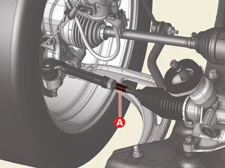
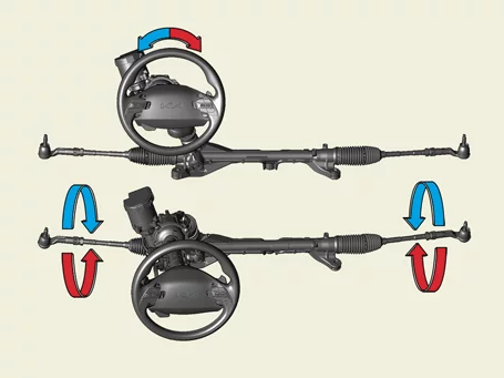
Turn the tie rod turnbuckle (A) clockwise or counterclockwise to adjust the steering wheel off center.
[Tie rod turnbuckle rotation according to steering wheel off
center]
|
| 8. |
Tighten the tie rod end nut (A) after adjustment.
|
| 9. |
Install the front wheel and tires.
(Refer to Suspension System - "Wheel")
|
| 10. |
Check the wheel alignment.
(Refer to Suspension System - "Alignment")
|
Suspension Ball Joints Inspection
| Inspection |
Visually check, must be free from injurious flaw and crack.
Suspension Mounting Bolts Inspection
| Inspection |
Visually check the loose mount bolt.
Tire (pressure & tread wear) Inspection
| Tire Pressure |
Tire Pressure
| 1. |
Check the tire pressure.
|
||||||||||||||
| Tire Rotation |
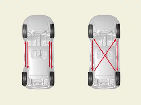
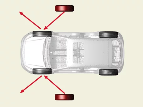
When directional or asymmetric tires applied, do not perform left/right or diagonal tire replacement.
Driving and braking performance may be poor which may affect safety.
|
Replace the tire in the direction shown by the arrow in the figure below.
Checking For Pull And Wander
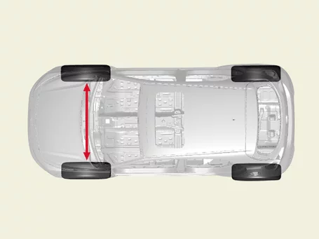
If the steering pulls to one side, rotate the tires according to the following wheel rotation procedure.
| 1. |
Rotate the front right and front left tires, and perform a road test in order to confirm vehicle
stability.
|
| 2. |
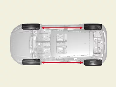
If the steering pulls to the opposite side, rotate the front and rear tires, and perform a road test
again.
|
| 3. |
If the steering continues to pull to one side, rotate the front right and left tires again, and perform a
road test.
|
| 4. |
If the steering continues to pull to the opposite side, replace the front wheels with new ones.
|
Rear Differential Carrier Oil Lubricant
| Lubricant |
| Rear differential carrier (AWD) |
|
Item |
Lubricant |
Quantity |
|
Rear differential carrier oil |
Hypoid gear oil SK HCT-5 gear oil 75W/85 or equivalent |
About 0.58 ℓ (0.15 U.S.gal., 0.52 U.S.qt., 0.51 Imp.qt.) |
Rear Differential Carrier Oil Inspection
| Inspection |
| 1. |
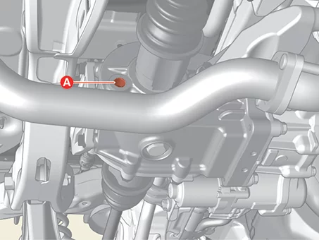
Check for traces of oil leakage around the filler plug.
|
| 2. |
Remove the filler plug and check that gear oil is visible through the filler plug hole (A).
|
Rear Differential Carrier Oil Replacement
| Replacement |
| 1. |
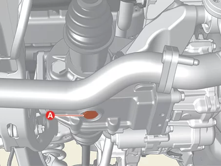
Remove the drain plug (A) and drain gear oil, and then reinstall the drain plug (A).
|
| 2. |
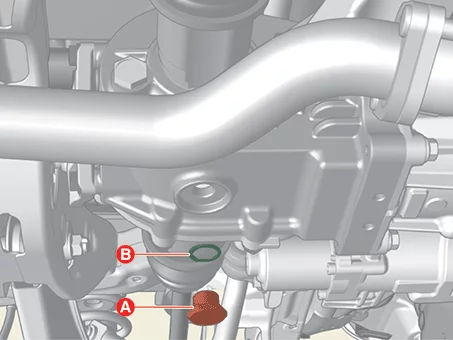
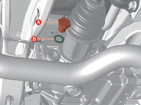
Remove the filler plug (A) and gasket (B).
|
| 3. |
Fill new gear oil through the filler plug hole (A).
|
| 4. |
Install the filler plug (A) and filler gasket (B).
|
| 5. |
Start the vehicle and check for oil leaks from the differential carrier assembly.
|
Transfer Oil Lubricant
| Lubricant |
| Fluid |
|
Item |
Capacity |
| Transfer oil |
About 0.50 ℓ (0.13 U.S.gal., 0.52 U.S.qt, 0.43 Imp.qt.) |
| Grease |
|
Item |
Recommended grease |
Capacity |
|
Transfer spline |
TECHRUBE MEGAMAX-ALPHA, CASMOLY CSG 101 M or equivalent |
2.0 - 5.0 g |
|
Coupling spline |
2.0 - 6.0 g |
Transfer Oil Inspection
| Inspection |
Inspect and replace transfer oil every 4 years or 60,000 km (37,000 mile).
|

| 1. |
Remove the engine room under cover.
G 1.6 MPI GAMMA (Refer to Engine Mechanical System - "Engine Room Under
Cover")
G 1.6 T-GDI GAMMA II (Refer to Engine Mechanical System - "Engine Room
Under Cover")
G 2.0 MPI NU (Refer to Engine Mechanical System - "Engine Room Under
Cover")
|
| 2. |
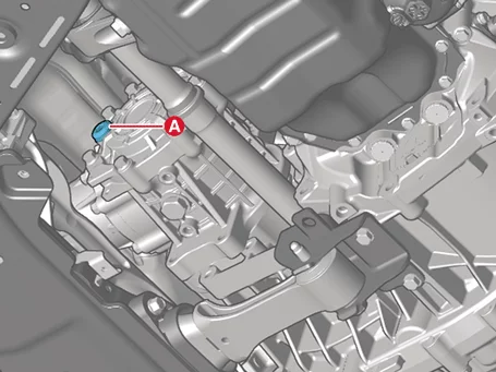
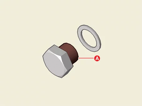
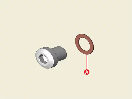
Remove the filler plug (A).
|
| 3. |
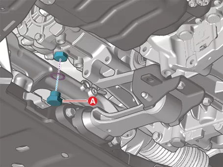
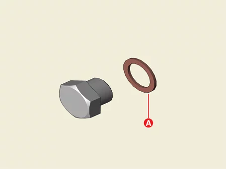
Remove the drain plug (A), wait for at least 10 minutes until the oil is fully drained, and then
reinstall the drain plug.
|
| 4. |
Check the amount of drained oil and fill the specified amount of oil through the filler plug hole.
|
| 5. |
Install the filler plug (A).
|
| 6. |
Install the engine room under cover.
G 1.6 MPI GAMMA (Refer to Engine Mechanical System - "Engine Room Under
Cover")
G 1.6 T-GDI GAMMA II (Refer to Engine Mechanical System - "Engine Room
Under Cover")
G 2.0 MPI NU (Refer to Engine Mechanical System - "Engine Room Under
Cover")
|
Transfer Oil Replacement
| Replacement |
| 1. |
Remove the engine room under cover.
G 1.6 MPI GAMMA (Refer to Engine Mechanical System - "Engine Room Under
Cover")
G 1.6 T-GDI GAMMA II (Refer to Engine Mechanical System - "Engine Room
Under Cover")
G 2.0 MPI NU (Refer to Engine Mechanical System - "Engine Room Under
Cover")
|
| 2. |
Remove the drain plug (A) and drain transfer oil, and then reinstall the drain plug (A).
|
| 3. |
Remove the filler plug (A) and refill with oil.
|
| 4. |
Install the filler plug (A).
|
| 5. |
Install the engine room under cover.
G 1.6 MPI GAMMA (Refer to Engine Mechanical System - "Engine Room Under
Cover")
G 1.6 T-GDI GAMMA II (Refer to Engine Mechanical System - "Engine Room
Under Cover")
G 2.0 MPI NU (Refer to Engine Mechanical System - "Engine Room Under
Cover")
|


Other information:
Kia Seltos SP2 (2021-2026) Service Manual: Electronic Parking Brake (EPB) Description and Operation
Description The Electric Parking Brake (EPB) is a parking brake system that operates the actuators of each caliper using an electrical signal via button operation, unlike a parking brake operated by a lever or pedal. The EPB has the function to engage the parking brake when the vehicle is stationary, to assist in braking in emergencies due to brake failure, and to engage the parking brake automatically when the engine off.Kia Seltos SP2 (2021-2026) Service Manual: Folding key immobilizer system
Your Kia Seltos may be equipped with an electronic engine immobilizer system designed to help reduce the risk of unauthorized vehicle use. The immobilizer system consists of a small transponder built into the ignition key and electronic control components installed inside the vehicle. When you insert the ignition key into the ignition switch and turn it to the ON position, the Kia Seltos immobilizer system checks the key and verifies whether it is valid for the vehicle.