
Kia Seltos: Heating,Ventilation And Air Conditioning / Controller
Contents:
- Heater & A/C Control Unit (Manual) Connector and Terminal Information
- Heater & A/C Control Unit (Manual) Removal and Installation
- Heater & A/C Control Unit (Auto) On Vehicle Inspection
- Heater & A/C Control Unit (Auto) Connector And Terminal Function
- Heater & A/C Control Unit (Auto) Removal and Installation
Heater & A/C Control Unit (Manual) Connector and Terminal Information
| Connector And Terminal Function |
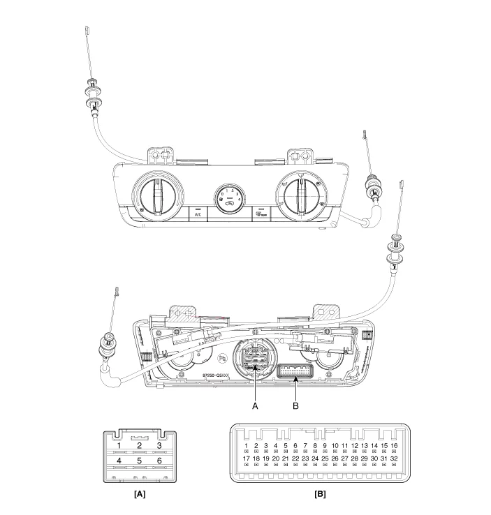
|
Pin NO |
Connector A |
Pin NO |
Connector A |
|
1 |
Battery ( + ) |
17 |
IG 2 |
|
2 |
ISG Battery ( + ) |
18 |
IG 1 |
|
3 |
ILL ( + ) |
19 |
- |
|
4 |
Sensor REF (+5 V) |
20 |
Max blower on signal |
|
5 |
- |
21 |
PTC Relay 3 |
|
6 |
- |
22 |
PTC Relay 2 |
|
7 |
Intake actuator feedback |
23 |
PTC on signal |
|
8 |
Evaporator temperature sensor ( + ) |
24 |
- |
|
9 |
Ambient temperature sensor ( + ) |
25 |
P-CAN (High) |
|
10 |
Mode actuator (Vent) |
26 |
P-CAN (Low) |
|
11 |
Mode actuator (Def) |
27 |
- |
|
12 |
Heateds IND (Front) |
28 |
ECV ( + ) |
|
13 |
HTD (Rear defroster indicator lamp) |
29 |
ECV ( - ) |
|
14 |
Detent out ( - ) |
30 |
- |
|
15 |
Blower on signal to common |
31 |
Sensor ground |
|
16 |
ILL ( - ) |
32 |
Ground |
Heater & A/C Control Unit (Manual) Removal and Installation
| Removal |
| 1. |
Disconnect the negative ( - ) battery terminal.
|
| 2. |
Remove the glove box.
(Refer to Body - "Glove Box")
|
| 3. |
Remove the crash pad lower panel.
(Refer to Body - "Crash Pad Panel")
|
| 4. |
Remove the passenger's side crash pad garnish.
(Refer to Body - "Crash Pad Garnish")
|
| 5. |
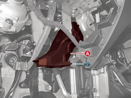
Remove the driver's side shower duct (A) after removing the screw.
|
| 6. |
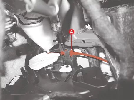
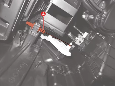
Disconnect the heater & A/C control unit cable (A).
[Driver's Side]
[Passenger's Side]
|
| 7. |
Remove the heater & A/C control unit (A) after removing the screws.
|
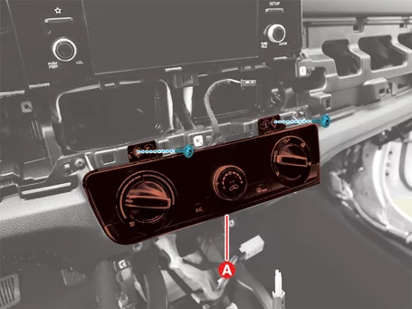
| 8. |
Disconnect the heater & A/C control unit connectors (A).
|
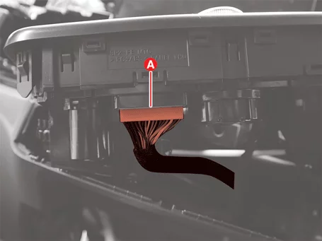
| Installation |
| 1. |
Install in reverse order of removal.
|
Heater & A/C Control Unit (Auto) On Vehicle Inspection
| On Vehicle Inspection |
| Self Diagnosis |
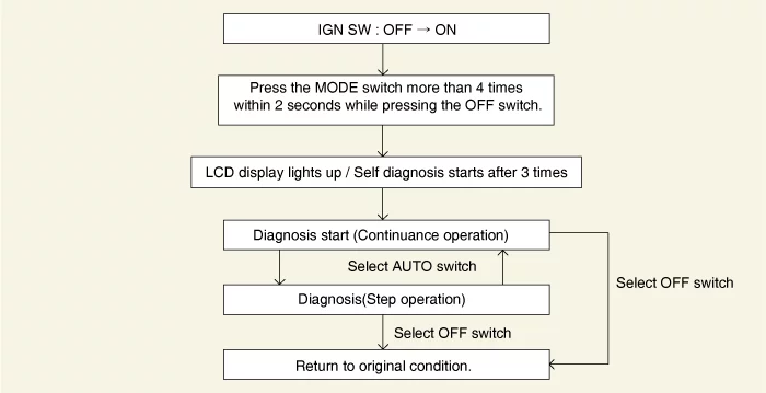
|

| 1. |
How to display fault codes
|


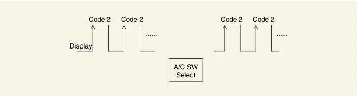
| 2. |
For troubleshooting procedures, refer to the DTC code.
|
Heater & A/C Control Unit (Auto) Connector And Terminal Function
| Connector And Terminal Function |
[Display Audio Type]
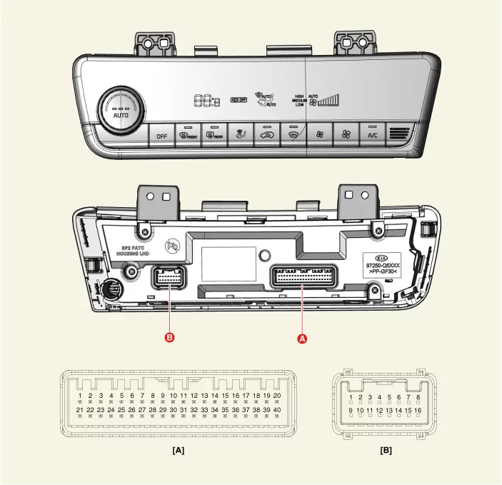
|
Pin No |
Connector A |
Connector B |
|
1 |
Battery ( + ) |
- |
|
2 |
ISG Battery ( + ) |
- |
|
3 |
ILL ( + ) (TAIL) |
- |
|
4 |
Sensor ground REF (+5 V) |
Defogging actuator (Feedback) |
|
5 |
Mode control actuator (Feedback) |
Defogging actuator (Open) |
|
6 |
Temperature actuator (Feedback) |
Defogging actuator (Close) |
|
7 |
Intake actuator (Feedback) |
- |
|
8 |
Evaporator temperature sensor ( + ) |
Rear glass defogger indicator |
|
9 |
Ambient temperature senor ( + ) |
Rear glass defogger switch |
|
10 |
Mode control actuator (Vent) |
- |
|
11 |
Mode control actuator (Def) |
- |
|
12 |
Temperature actuator (Cool) |
Defog (TEMP) |
|
13 |
Temperature actuator (Warm) |
Defog (SCK) |
|
14 |
Intake actuator (Fresh) |
Defog (DATA) |
|
15 |
Intake actuator (Recirculation) |
- |
|
16 |
HTD (Rear defog indicator) |
Ground |
|
17 |
Rear defogging switch |
|
|
18 |
Blower relay |
|
|
19 |
- |
|
|
20 |
Rheostat ILL ( + ) |
|
|
21 |
IG 2 |
|
|
22 |
IG 1 |
|
|
23 |
Blower motor ( + ) |
|
|
24 |
Photo sensor ( - ) |
|
|
25 |
- |
|
|
26 |
- |
|
|
27 |
- |
|
|
28 |
- |
|
|
29 |
- |
|
|
30 |
- |
|
|
31 |
Detent out ( - ) |
|
|
32 |
- |
|
|
33 |
P-CAN (HIGH) |
|
|
34 |
P-CAN (LOW) |
|
|
35 |
FET (Drain Feedback) |
|
|
36 |
FET (Gate) |
|
|
37 |
ECV ( + ) |
|
|
38 |
ECV ( - ) |
|
|
39 |
Sensor ground ( - ) |
|
|
40 |
Ground ( - ) |
[AVNT Type]
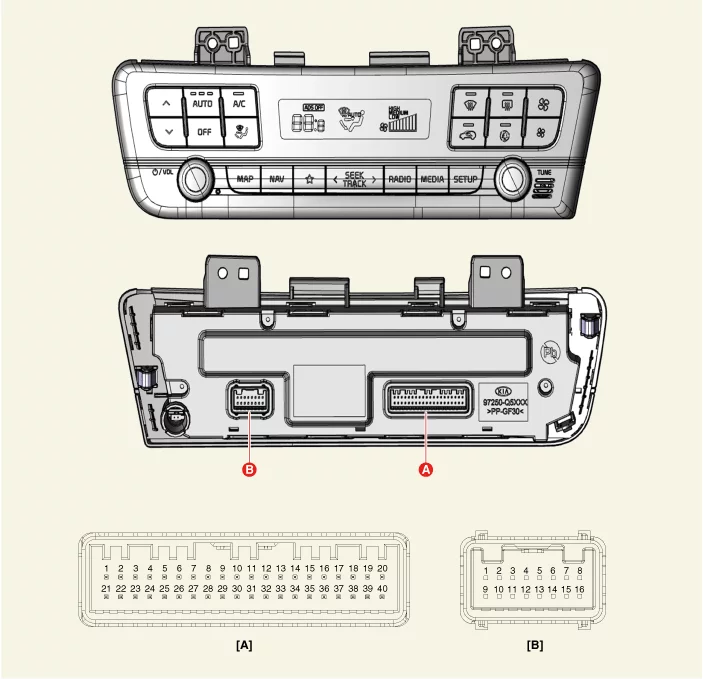
|
Pin No |
Connector A |
Connector B |
|
1 |
Battery ( + ) |
- |
|
2 |
ISG Battery ( + ) |
- |
|
3 |
ILL ( + ) (TAIL) |
- |
|
4 |
Sensor ground REF (+5 V) |
Defogging actuator (Feedback) |
|
5 |
Mode control actuator (Feedback) |
Defogging actuator (Open) |
|
6 |
Temperature actuator (Feedback) |
Defogging actuator (Close) |
|
7 |
Intake actuator (Feedback) |
- |
|
8 |
Evaporator temperature sensor ( + ) |
Rear glass defogger indicator |
|
9 |
Ambient temperature senor ( + ) |
Rear glass defogger switch |
|
10 |
Mode control actuator (Vent) |
- |
|
11 |
Mode control actuator (Def) |
- |
|
12 |
Temperature actuator (Cool) |
Defog (TEMP) |
|
13 |
Temperature actuator (Warm) |
Defog (SCK) |
|
14 |
Intake actuator (Fresh) |
Defog (DATA) |
|
15 |
Intake actuator (Recirculation) |
- |
|
16 |
HTD (Rear defog indicator) |
Ground |
|
17 |
Rear defogging switch |
|
|
18 |
Blower relay |
|
|
19 |
- |
|
|
20 |
Rheostat ILL ( + ) |
|
|
21 |
IG 2 |
|
|
22 |
IG 1 |
|
|
23 |
Blower motor ( + ) |
|
|
24 |
Photo sensor ( - ) |
|
|
25 |
- |
|
|
26 |
- |
|
|
27 |
- |
|
|
28 |
- |
|
|
29 |
- |
|
|
30 |
AVNT head unit keyboard reset |
|
|
31 |
Detent out ( - ) |
|
|
32 |
- |
|
|
33 |
P-CAN (HIGH) |
|
|
34 |
P-CAN (LOW) |
|
|
35 |
FET (Drain Feedback) |
|
|
36 |
FET (Gate) |
|
|
37 |
ECV ( + ) |
|
|
38 |
ECV ( - ) |
|
|
39 |
Sensor ground ( - ) |
|
|
40 |
Ground ( - ) |
Heater & A/C Control Unit (Auto) Removal and Installation
| Removal |
| 1. |
Remove the center air vent.
(Refer to Body - "Crash Pad Air Vent")
|
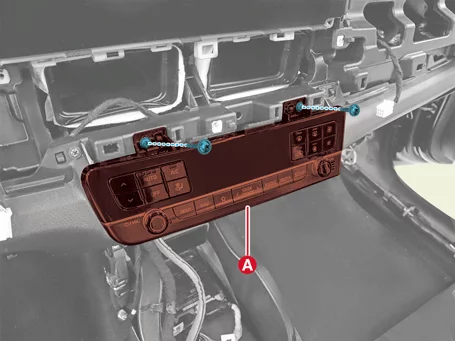
| 2. |
Remove the heater and air conditioner control unit (A) after removing the screws.
|
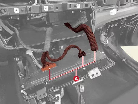
| 3. |
Disconnect the heater and air conditioner control unit hose and connectors (A).
|
| Installation |
| 1. |
Install in reverse order of removal.
|


Other information:
Kia Seltos SP2 (2021-2026) Service Manual: Light bulbs
Light bulbs are installed in various areas of the Kia Seltos to provide exterior lighting, interior illumination, and visual signals for other drivers. Properly working lamps help improve visibility, safety, and communication on the road. Bulb replacement precaution Keep spare bulbs with the correct wattage rating available in case replacement is needed during an emergency.Kia Seltos SP2 (2021-2026) Service Manual: Smart key immobilizer system
The Kia Seltos smart key immobilizer system helps protect the vehicle from theft. If an incorrectly coded key or an unauthorized electronic device is used, the vehicle's power system may be disabled and the engine may not start. When the ENGINE START/STOP button is placed in the ON position, the immobilizer system indicator should illuminate briefly and then turn off.