Kia Seltos: Heating,Ventilation And Air Conditioning / Blower
Contents:
- Components and Components Location
- On Vehicle Inspection
- Blower Unit Removal and Installation
- Blower Motor Removal and Installation
- Blower Motor Inspection
- Climate Control Air Filter Description and Operation
- Climate Control Air Filter Replacement
- Intake Actuator Description and Operation
- Intake Actuator Removal and Installation
- Intake Actuator Inspection
- Blower Resistor Description and Operation
- Blower Resistor Removal and Installation
- Blower Resistor Inspection
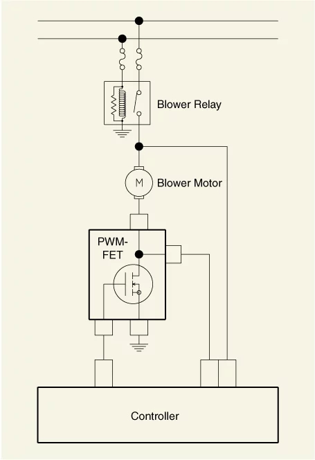
- PWM-FET Description and Operation
- PWM-FET Removal and Installation
- PWM-FET Inspection
Components and Components Location
| Component |
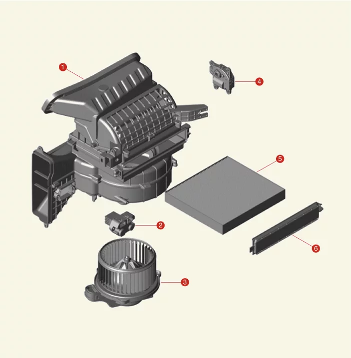
| 1. Blower Unit 2. PWM-FET 3. Blower Motor |
4. Intake Actuator 5. Climate Control Air Filter 6. Climate Control Air Filter Cover |
On Vehicle Inspection
| On Vehicle Inspection |
| Diagnosis with KDS |
| 1. |
The heating,ventilation and air conditioning system can be more quickly diagnosed for problems with the
KDS (Refer to "DTC guide").
|

Blower Unit Removal and Installation
| Removal |
| 1. |
Separate the heater unit and blower unit.
(Refer to Heater - "Heater Unit")
|
| Installation |
| 1. |
Install in reverse order of removal.
|
Blower Motor Removal and Installation
| Removal |
| 1. |
Disconnect the battery negative ( - ) terminal.
|
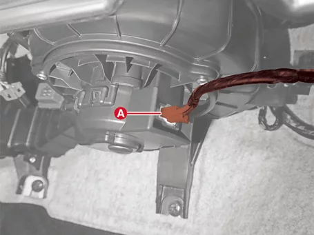
| 2. |
Disconnect the blower motor connector (A).
|
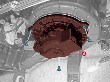
| 3. |
Remove the blower motor (A) after removing the screws.
|
| Installation |
| 1. |
Install in reverse order of removal.
|
Blower Motor Inspection
| Inspection |
| 1. |
Turn IG OFF.
|
| 2. |
Disconnect the blower motor connector.
|
| 3. |
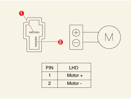
Apply voltage to the ( + ) terminal and ground the ( - ) terminal to check whether the motor is running.
|
| 4. |
If the blower motor does not work, replace it with a new blower motor.
|
Climate Control Air Filter Description and Operation
| Description |
The air filter for the air conditioner installed on the blower unit removes foreign substances or odors. The
particle filter not only removes general dust but also serves as a odor-removing filter to maintain a comfortable
indoor environment.
Climate Control Air Filter Replacement
| Replacement |
|

| 1. |
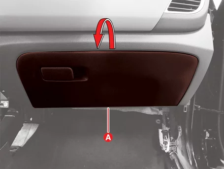
Open the glove box (A).
|
| 2. |
Remove the air damper (A).
|
| 3. |
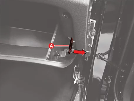
Press the stopper of the glove box (A) in the direction of the arrow to lower it.
|
| 4. |
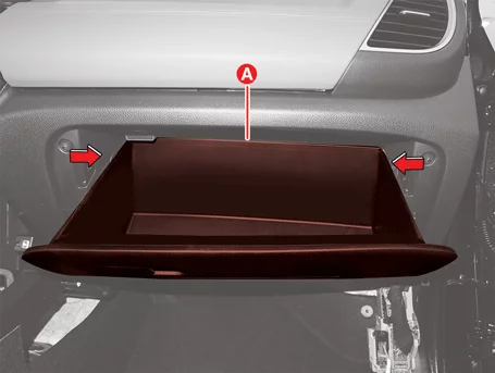
Remove the air filter cover (A) for air conditioning by pressing the filter cover knob in the direction
of the arrow.
|
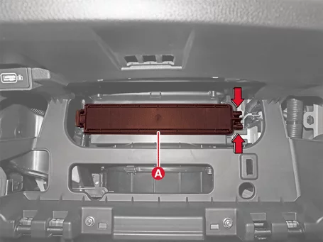
| 5. |
Replace the air filter (A) for air conditioning.
|
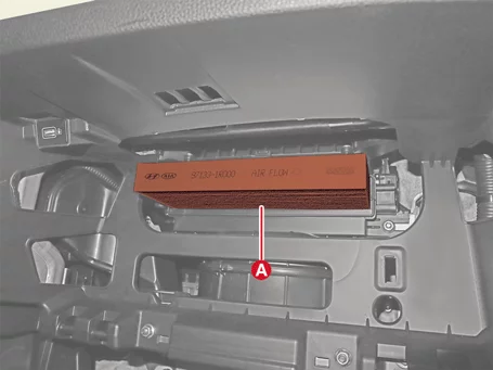
| 6. |
Install in reverse order of removal.
|
Intake Actuator Description and Operation
| Description |
| • |
The intake actuator installed on the blower unit adjusts the intake door according to the signal from the
control unit.
|
| • |
Press the Fresh air mode/Recirculation mode switch to switch to the recirculation or fresh air intake
mode.
|
Intake Actuator Removal and Installation
| Removal |
| 1. |
Remove the Integrated Body Control Unit (IBU).
(Refer to Body Electrical System - "Integrated Body Control Unit
(IBU)")
|
| 2. |
Disconnect the intake actuator connector (A).
|
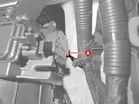
| 3. |
Remove the intake actuator (A) after removing the screws.
|
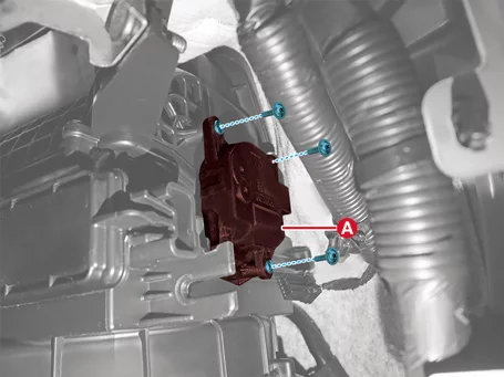
| Installation |
| 1. |
Install in reverse order of removal.
|
Intake Actuator Inspection
| Inspection |
| 1. |
Turn the IG OFF.
|
| 2. |
Disconnect the intake actuator connector.
|
| 3. |
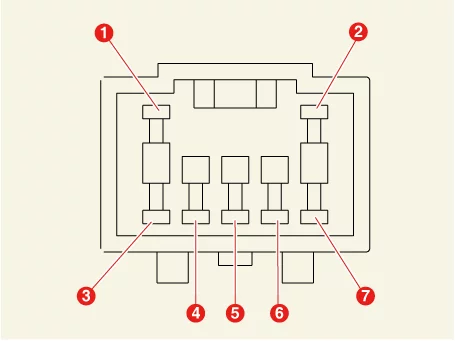
Connect the power ( + ) terminal to the intake actuator connector terminal 3 and the ( - ) terminal to
the 4 terminal to check whether the actuator is driven in the outside air direction.
|
| 4. |
Connect the intake actuator connector.
|
| 5. |
Turn the IG ON.
|
| 6. |
Measure the voltage across terminals 6 - 7.
|
| 7. |
If the measured voltage does not match with the specification, replace it with a new intake actuator.
|
Blower Resistor Description and Operation
| Description |
The fan speed is adjusted by precisely controlling the voltage applied to the blower motor.
Blower Resistor Removal and Installation
| Removal |
| 1. |
Remove the crash pad center panel.
(Refer to Body - "Crash Pad Lower Panel")
|
| 2. |
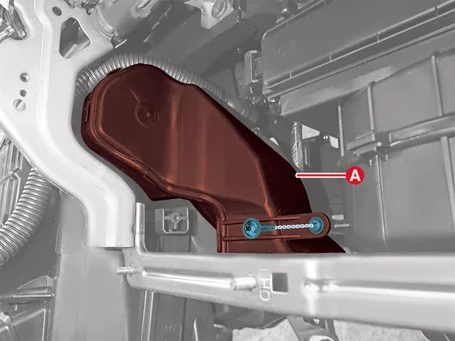
Remove the passenger's side shower duct (A) after removing the screw.
|
| 3. |
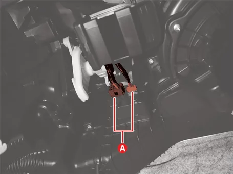
Disconnect the blower resistor connectors (A).
|
| 4. |
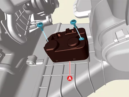
Remove the blower resistor (A) after removing the screws.
|
| Installation |
| 1. |
Install in reverse order of removal.
|
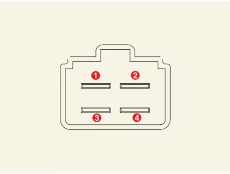
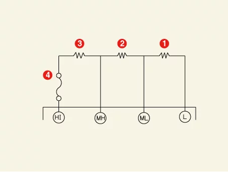
Blower Resistor Inspection
| 1. |
Measure the resistance between the terminals.
|
| 2. |
If measured resistance is not within specification, the blower resistor must be replaced.
|
PWM-FET Description and Operation
| Description |
The blower fan speed is adjusted by precisely controlling the voltage applied to the blower motor.
PWM-FET Removal and Installation
| Removal |
| 1. |
Remove the crash pad center panel.
(Refer to Body - "Crash Pad Lower Panel")
|
| 2. |
Remove the passenger's side shower duct (A) after removing the screw.
|
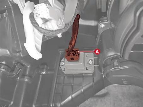
| 3. |
Disconnect the blower resistor connector (A).
|
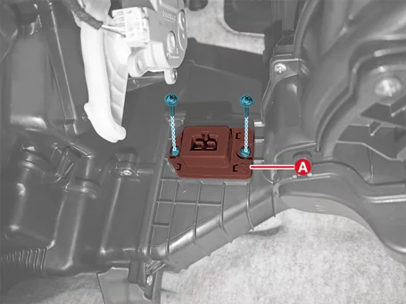
| 4. |
Remove the blower resistor (A) after removing the screws.
|
| Installation |
| 1. |
Install in reverse order of removal.
|
PWM-FET Inspection
| Inspection |
| 1. |
Turn the IG ON.
|
| 2. |
The air conditioner controls the speed of the blower motor by controlling the gate terminal of the
PWM-FET.
|
| 3. |
Measure the voltage between the terminals of the blower motor by manually operating the control switch.
|