
Kia Seltos SP2 (2021-2026) Service Manual / Engine Mechanical System / Cooling System
Kia Seltos: Engine Mechanical System / Cooling System
Contents:
- Components and Components Location
- Troubleshooting
- Coolant Replacement
- Cooling Fan Components and Components Location
- Cooling Fan Specification
- Cooling Fan Removal and Installation
- Cooling Fan Inspection
- Cooling Fan Disassembly and Reassembly
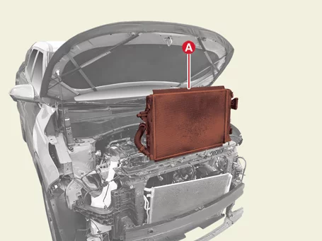
- Radiator Removal and Installation
- Radiator Inspection
- Water Temperature Control Assembly Components and Components Location
- Water Temperature Control Assembly Removal and Installation
- Water Inlet Fitting Components and Components Location
- Water Inlet Fitting Removal and Installation
- Water Pump Components and Components Location
- Water Pump Troubleshooting
- Water Pump Removal and Installation
Components and Components Location
| Component |
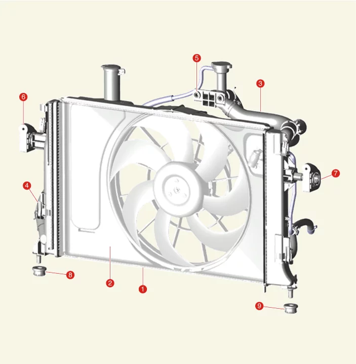
| 1. Cooling Fan
Assembly 2. Radiator 3. Radiator Upper Hose 4. Radiator Lower Hose 5. Filler Neck Assembly |
6. Radiator Upper
Mounting Bracket [RH] 7. Radiator Upper Mounting Bracket [LH] 8. Radiator Lower Mounting Insulator [RH] 9. Radiator Lower Mounting Insulator [LH] |
Troubleshooting
| Engine Overheat Troubleshooting |
| Inspection |
Repair |
||||
| Visual Inspection |
Inspect for shortage of coolant in reservoir tank. |
Reinspect after refilling coolant. |
|||
Inspect for coolant pollution after removing radiator cap.
|
Reinspect after replacing coolant. |
||||
|
Inspect for leakage and loose coolant hoses (radiator hose, heater hose, oil cooler hose, etc.). |
Reinspect for leakage after reinstalling hoses and clamps. |
||||
|
Inspect for leakage on water temperature control assembly mounting part. |
Reinspect for leakage after replacing O-ring. |
||||
|
Inspect for leakage on water inlet fitting mounting part. |
Reinspect for leakage after replacing O-ring. |
||||
|
Inspect drive belt (for normal operation of water pump). |
Adjust or replace drive belt tension |
||||
| Inspect for leakage on water pump gasket mounting part. |
Reinspect for leakage after replacing gasket. |
||||
|
Reinspect for leakage after tightening to the specified torque. |
|||||
| Inspect for loose coolant temperature sensor, cooling fan connector and pin. |
Reinstall loose connector. |
||||
|
Replace relevant part if connector pin is damaged. |
|||||
|
Inspect operation status of cooling fan. - Check operation status by switching ON/OFF the heater control A/C.
|
Check mounting status of ground cable. |
||||
|
Diagnostic Device |
Inspect self-diagnostic code using KDS. |
Check coolant temperature sensor, wiring, connector, etc. |
|||
| Component Inspection |
Inspect water pump impeller. |
Replace the water pump. |
|||


Coolant Replacement
| Engine Coolant Refilling And Air Bleeding |
When replenishing coolant, be careful not to spill on the belt, electrical devices.
|
| 1. |
Make sure the engine and radiator are cool to the touch.
|
| 2. |
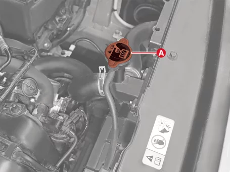
Remove the pressure cap (A).
|
| 3. |
Remove the engine room under cover.
(Refer to Engine and Transaxle Assembly - "Engine Room Under
Cover")
|
| 4. |
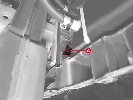
Remove the drain plug (A) and drain the coolant.
|
| 5. |
After draining the coolant, re-tighten the drain plug.
|
| 6. |
Drain coolant and inside the reservoir tank, and then clean it.
|
| 7. |
Install the coolant refill tank on the radiator and then add the mixture of anti-freeze and water (55 -
60%).
|

| 8. |
Start the engine and run until coolant circulates. When the cooling fan operates and coolant circulates,
refill coolant through the reservoir tank.
|
| 9. |
Repeat step 12 until the cooling fan operates 3 - 5 times and bleed air sufficiently out of the cooling
system.
|
| 10. |
Fill the reservoir tank to the "MAX" (or "FULL") line with coolant and tighten the pressure cap.
|
| 11. |
Install the engine room under cover.
(Refer to Engine and Transaxle Assembly - "Engine Room Under
Cover")
|
Cooling Fan Components and Components Location
| Component |
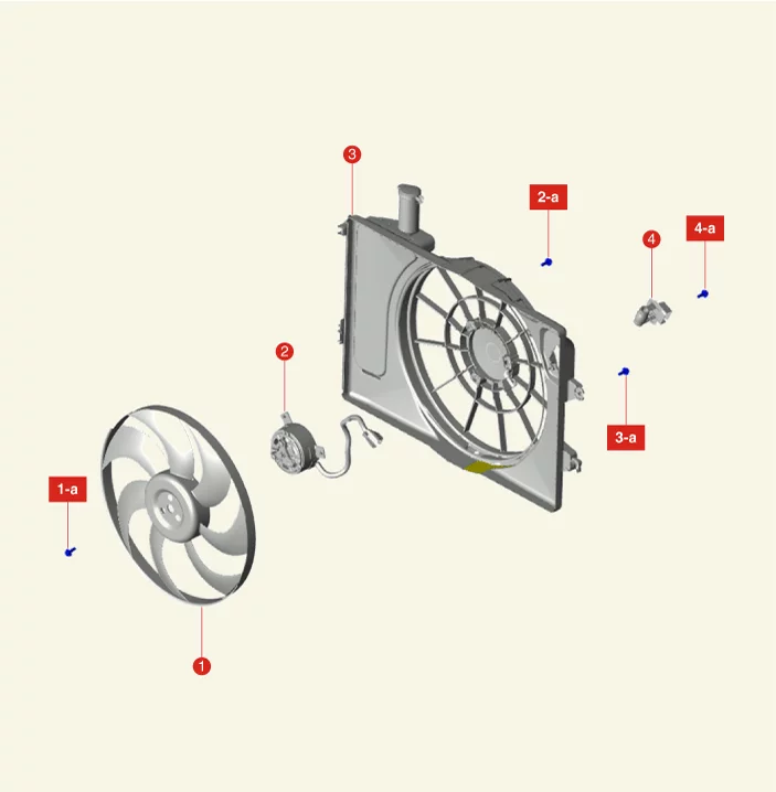
| 1. Cooling Fan 1-a. 2.7 - 3.2 N·m (0.28 - 0.33 kgf·m, 2 - 2.4 lb·ft, 24.3 - 28.6 lb·in) 2. Cooling Fan motor 2-a. 3.9 - 5.9 N·m (0.4 - 0.6 kgf·m, 2.9 - 4.3 lb·ft, 34.7 - 52.1 lb·in) |
3. Cooling Fan Shroud 3-a. 4.9 - 7.8 N·m (0.5 - 0.8 kgf·m, 3.6 - 5.8 lb·ft, 43.4 - 69.4 lb·in) 4. Cooling Fan Resistor 4-a. 0.2 - 2.5 N·m (0.018 - 0.25 kgf·m, 0.1 - 1.8 lb·ft, 1.6 - 21.7 lb·in) |
Cooling Fan Specification
| Specification |
| Item |
Specification |
| Fan type |
PULLER |
| Fan speed control |
Resisor |
| Air volume (m³/h) |
1,950 (2,550) - 8% min. |
| Fan speed (rpm) |
1,650 ± 8% |
| Current consumption (A) |
11.7 + 10% max. |
Cooling Fan Removal and Installation
| Removal |
Cooling Fan Assembly
| 1. |
Disconnect the battery negative ( - ) terminal.
|
| 2. |
Remove the air duct.
(Refer to Intake and Exhaust System – "Air Cleaner")
|
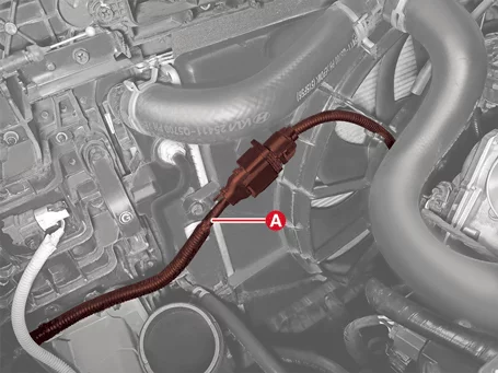
| 3. |
Disconnect resistor connector (A).
|
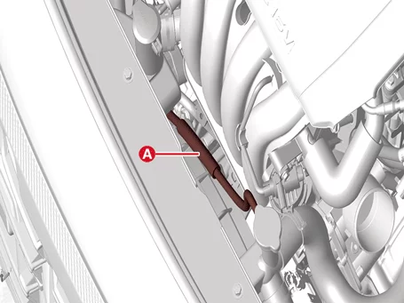
| 4. |
Separate the reservoir tank hose (A).
|
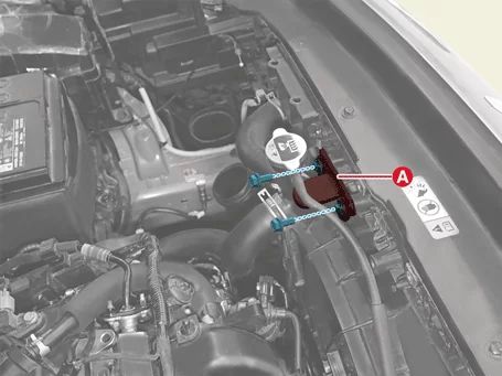
| 5. |
Separate the filler neck assembly (A) after removing bolts.
|
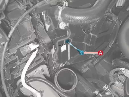
| 6. |
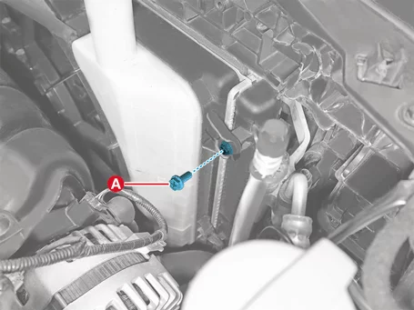
Remove the cooling fan bolts (A).
[LH]
[RH]
|
| 7. |
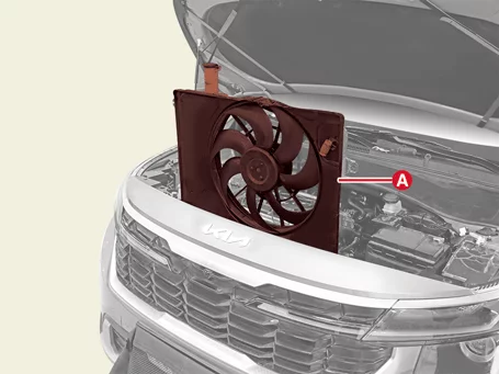
Remove the cooling fan assembly (A).
|
| Register |
| 1. |
Disconnect the battery negative ( - ) terminal.
|
| 2. |
Remove the air duct.
(Refer to Intake and Exhaust System - "Air Cleaner")
|
| 3. |
Disconnect resistor connector (A).
|
| 4. |
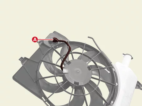
Disconnect the cooling fan motor connector (A).
|
| 5. |
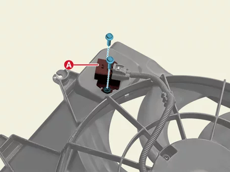
Remove the resistor (A) after removing bolts.
|
| Reassembly |
| Cooling fan assembly |
| 1. |
Install in reverse order of removal.
|
| Register |
| 1. |
Install in reverse order of removal.
|
Cooling Fan Inspection
| Inspection |
Fan motor
| 1. |
After connecting the KDS, force the cooling fan motor.
[Fan motor low speed]
[Fan motor high speed]
|
Cooling Fan Disassembly and Reassembly
| Disassembly |
| 1. |
Disconnect the cooling fan motor connector (A).
|
| 2. |
Remove the cooling fan (A) from the cooling fan shroud.
|
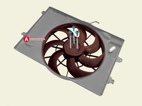
| 3. |
Remove the cooling fan motor from the cooling fan shroud after removing bolts.
|
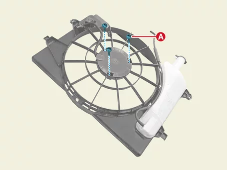
| Reassembly |
| 1. |
Install in reverse order of removal.
|
Radiator Removal and Installation
| Removal and Installation |
| 1. |
Remove the cooling fan.
(Refer to Cooling System - "Cooling Fan")
|
| 2. |
Drain the coolant.
(Refer to Cooling System - "Coolant")
|
| 3. |
Separate the radiator upper hose (A) after releasing the clamp.
|
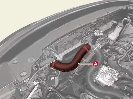
| 4. |
Separate the radiator lower hose (A) after releasing the clamp.
|
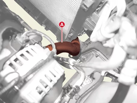
| 5. |
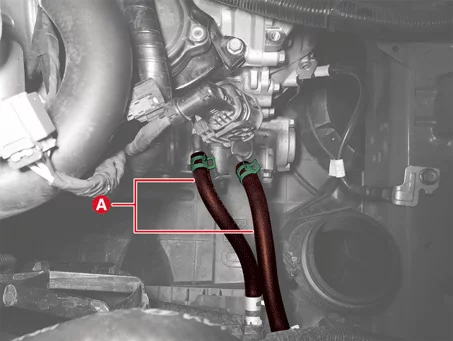
Separate the IVTF cooler hoses (A) after releasing the clamp.
|
| 6. |
Remove the front bumper assembly.
(Refer to Body - "Front Bumper Assembly")
|
| 7. |
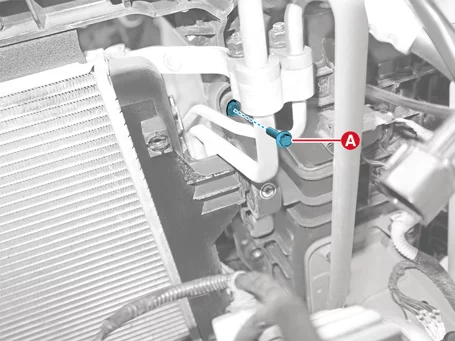
Remove the LH radiator upper mounting bracket bolt (A).
|
| 8. |
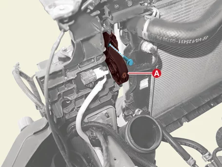
Remove the RH radiator upper mounting bracket (A) after removing RH radiator upper mounting bracket bolt.
|
| 9. |
Disconnect the ambient temperature sensor connector (A).
|
| 10. |
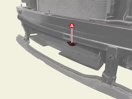
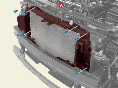
Remove the upper air guard (A) after removing bolts.
|
| 11. |
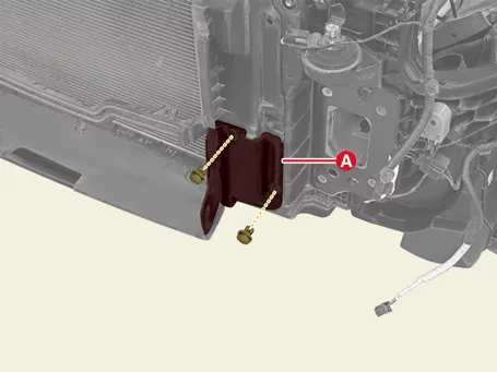
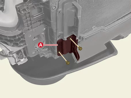
Remove the lower air guard (A), after removing the fastener.
[LH]
[RH]
|
| 12. |
Separate the conditioner (A).
|
| 13. |
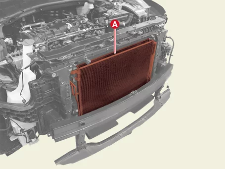
Remove the radiator (A).
|
| Installation |
| 1. |
Install in reverse order of removal.
|
| 2. |
Fill the coolant.
(Refer to Cooling System - "Coolant")
|
| 3. |
Start engine and check for leaks.
|
Radiator Inspection
| Inspection |
Radiator Leakage
| 1. |
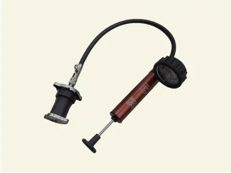
Wait until engine is cool, then carefully remove the pressure cap and fill the radiator with engine
coolant, then install it on the pressure tester.
|
| 2. |
Pressurize the pressure of the pressure tester to about 93 - 122 kPa (0.95 - 1.25 kg/cm², 13 - 17 psi)
|
| 3. |
Inspect for engine coolant leaks and a drop in pressure
|
| 4. |
Remove the tester and reinstall the pressure cap.
|
Water Temperature Control Assembly Components and Components Location
| Component |
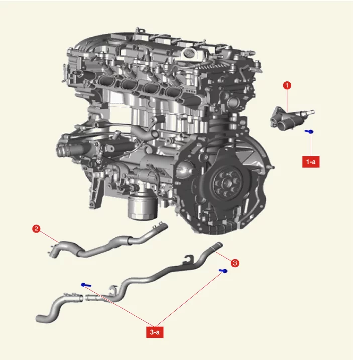
| 1. Water Temperature Control
Assembly 1-a. 9.8 - 11.8 N·m (1.0 - 1.2 kgf·m, 7.2 - 8.7 lb·ft) 2. Bypass Hose |
3. Heater Pipe & Hose
Assembly 3-a. 19.6 - 23.5 N·m (2.0 - 2.4 kgf·m, 14.5 - 17.4 lb·ft) |
Water Temperature Control Assembly Removal and Installation
| Removal |
Water temperature control assembly
| 1. |
Disconnect the battery negative ( - ) terminal.
|
| 2. |
Remove the engine room under cover.
(Refer to Engine and Transaxle Assembly - "Engine Room Under
Cover")
|
| 3. |
Drain the engine coolant.
(Refer to Cooling System - "Coolant")
|
| 4. |
Remove the air cleaner assembly.
(Refer to Intake and Exhaust System - "Air Cleaner")
|
| 5. |
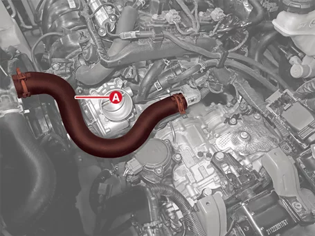
Separate the radiator upper hose (A) after releasing the clamp.
|
| 6. |
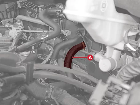
Release the clamp, and then disconnect the heater hose (A).
|
| 7. |
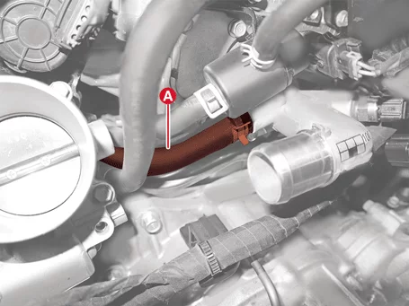
Separate the bypass hose (A) releasing the clamp.
|
| 8. |
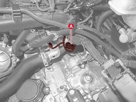
Disconnect the Engine Coolant Temperature Sensor (ECTS) and Purge Control Solenoid Valve (PCSV).
|
| 9. |
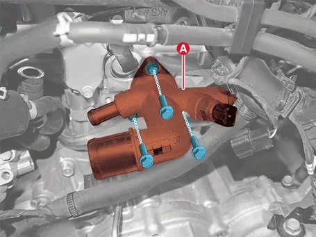
Remove the water temperature control assembly (A) after removing bolts.
|
Heating Pipe
| 1. |
Drain the engine coolant.
(Refer to Cooling System - "Coolant")
|
| 2. |
Remove the air cleaner assembly.
(Refer to Intake and Exhaust System - "Air Cleaner")
|
| 3. |
Remove the intake manifold.
(Refer to Intake and Exhaust System - "Intake Manifold")
|
| 4. |
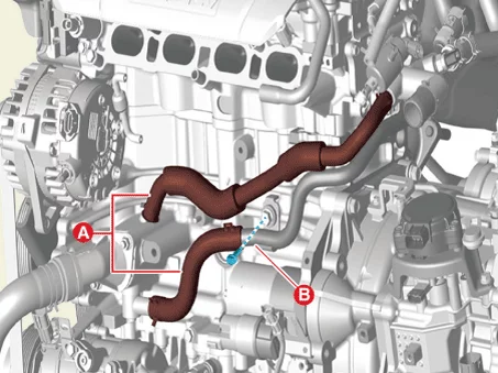
Remove the heater pipe bolt (B) and separate heater pipe hoses (A) after releasing the clamp.
|
| 5. |
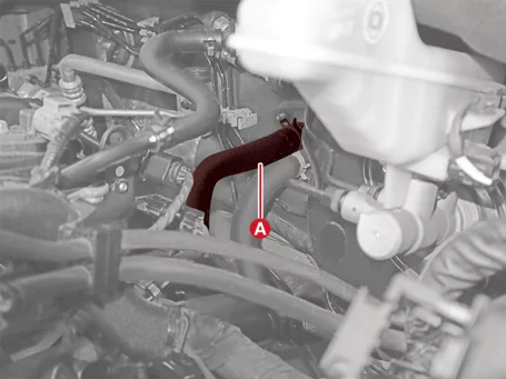
Separate the heater hose (A) after releasing the clamp.
|
| 6. |
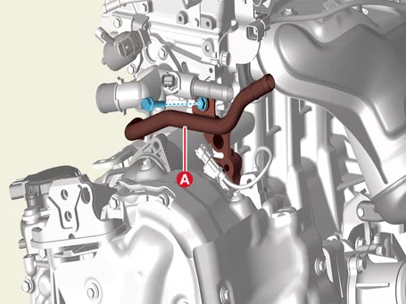
Remove the heater pipe (A) after removing bolt.
|
| Installation |
| Water temperature control assembly |
| 1. |
Install in reverse order of removal.
|
| 2. |
Fill the engine coolant.
(Refer to Cooling System - "Coolant")
|
| 3. |
Start engine and check for leaks.
|
| 4. |
Recheck engine coolant level.
|
| Heating Pipe |
| 1. |
Install in reverse order of removal.
|
| 2. |
Fill the engine coolant.
(Refer to Cooling System - "Coolant")
|
| 3. |
Start engine and check for leaks.
|
| 4. |
Recheck engine coolant level.
|
Water Inlet Fitting Components and Components Location
| Component |
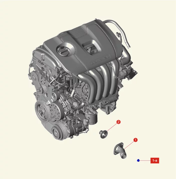
| 1. Water Inlet Fitting 1-a. 18.6 - 23.5 N·m (1.9 - 2.4 kgf·m, 13.7 - 17.4 lb·ft) |
2. Thermostat |
Water Inlet Fitting Removal and Installation
| Removal |
| 1. |
Remove the engine room under cover.
(Refer to Engine and Transaxle Assembly - "Engine Room Under
Cover")
|
| 2. |
Drain the coolant.
(Refer to Cooling System - "Coolant")
|
| 3. |
Separate the radiator lower hose (A) after releasing the clamp.
|
| 4. |
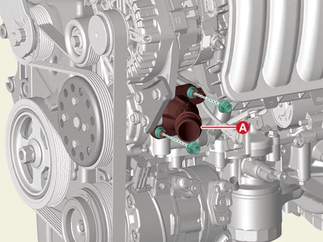
Remove the water inlet fitting (A) after removing the nuts.
|
| 5. |
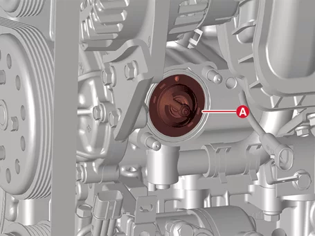
Remove the thermostat (A).
|
Installation
| 1. |
Install in reverse order of removal.
|
| 2. |
Fill the coolant.
(Refer to Cooling System - "Coolant")
|
| 3. |
Start engine and check for leaks.
|
| 4. |
Recheck engine coolant level.
|
Water Pump Components and Components Location
| Component |
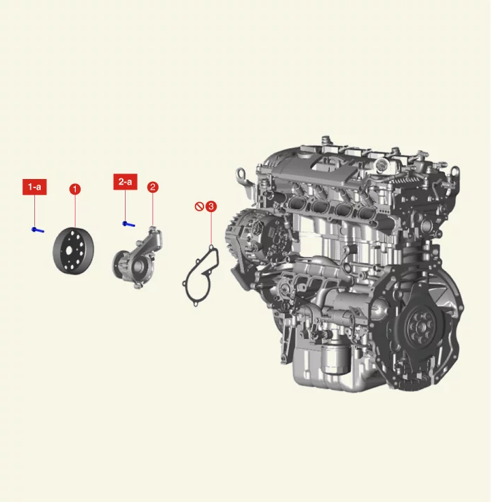
| 1. Water Pump Pulley 1-a. 9.8 - 11.8 N·m (1.0 - 1.2 kgf·m, 7.2 - 8.7 lb·ft) 2. Water Pump 2-a. 9.8 - 11.8 N·m (1.0 - 1.2 kgf·m, 7.2 - 8.7 lb·ft) 3. Water Pump Gasket |
Water Pump Troubleshooting
| Troubleshooting |
Coolant leakage
|
Symptom |
How to inspect |
Repair |
|||||||||
| Leak hole |
Visually check |
Check leaks after about ten-minute warming up. |
|
||||||||
| Gasket or bolt part leak |
Check water pump mounting bolt tightness. |
Tighten the water pump mounting bolts to the specified torque. |
|||||||||
| Check for gasket damage or dust ingress |
Replace the gasket and clean dust off. |
||||||||||
| Water Pump External Surface Leakage |
Check the water pump for cracks. |
Replace water pump in case of cracks. |
|||||||||
Noise
|
Symptom |
How to inspect |
Repair |
|||||||||||
|
Check the use of a stethoscope |
After starting the engine, check noise with a stethoscope. |
|
||||||||||
| Inspection after removing a drive belt |
After removing a drive belt, check noise again. |
|
|||||||||||
|
Inspection after removing a water pump |
Check water pump body & impeller interference |
Replace water pump in case of interference |
|||||||||||
Overheat
|
Symptom |
How to inspect |
Repair |
|||||||||
|
Inspection after removing a water pump |
Corrosion of the impeller wing |
|
||||||||
| Remove the impeller from the shaft |
Replace the water pump. |
||||||||||
Water Pump Removal and Installation
| Removal |
| 1. |
Remove the engine room under cover.
(Refer to Engine and Transaxle Assembly - "Engine Room Under
Cover")
|
| 2. |
Drain the coolant.
(Refer to Cooling System - "Coolant")
|
| 3. |
Remove the drive belt.
(Refer to Drive Belt System - "Drive Belt")
|
| 4. |
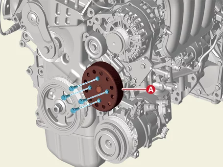
Remove the water pump pulley (A), after removing the bolts.
|
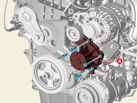
| 5. |
Remove the water pump (A) with gasket after removing bolts.
|
Installation
| 1. |
Install in reverse order of removal.
|
| 2. |
Fill the coolant.
(Refer to Cooling System - "Coolant")
|
| 3. |
Start engine and check for leaks.
|
| 4. |
Recheck engine coolant level.
|


Other information:
Kia Seltos SP2 (2021-2026) Service Manual: Safe Exit Warning (SEW)
Safe Exit Warning (SEW) in the Kia Seltos is designed to help protect occupants when the vehicle is stopped. If an approaching vehicle from the rear area is detected as a passenger opens a door, SEW may warn the driver with a warning message and an audible alert to help reduce the risk of a collision. CAUTION The warning timing may vary depending on the speed of the approaching vehicle and the surrounding traffic conditions.Kia Seltos SP2 (2021-2026) Service Manual: How does the air bag system operate?
Air bags in the Kia Seltos are activated and able to inflate only when the ENGINE START/STOP button has been turned to the ON position. The appropriate air bags inflate instantly during a serious frontal collision or side collision to help protect occupants from severe physical injury. There is no single fixed speed at which the air bags will inflate.