
Kia Seltos SP2 (2021-2026) Service Manual / Engine Mechanical System / Cylinder Block
Kia Seltos: Engine Mechanical System / Cylinder Block
Contents:
- Components and Components Location
- Water Jacket Insert Removal and Installation
- Drive Plate Removal and Installation
- Rear Oil Seal Replacement
- Piston and Connecting Rod Disassembly
- Piston and Connecting Rod Reassembly
- Piston and Connecting Rod Inspection
- Crankshaft Disassembly
- Crankshaft Reassembly
- Crankshaft Inspection
- Cylinder Block Disassembly
- Cylinder Block Reassembly
- Cylinder Block Inspection
Components and Components Location
| Component |
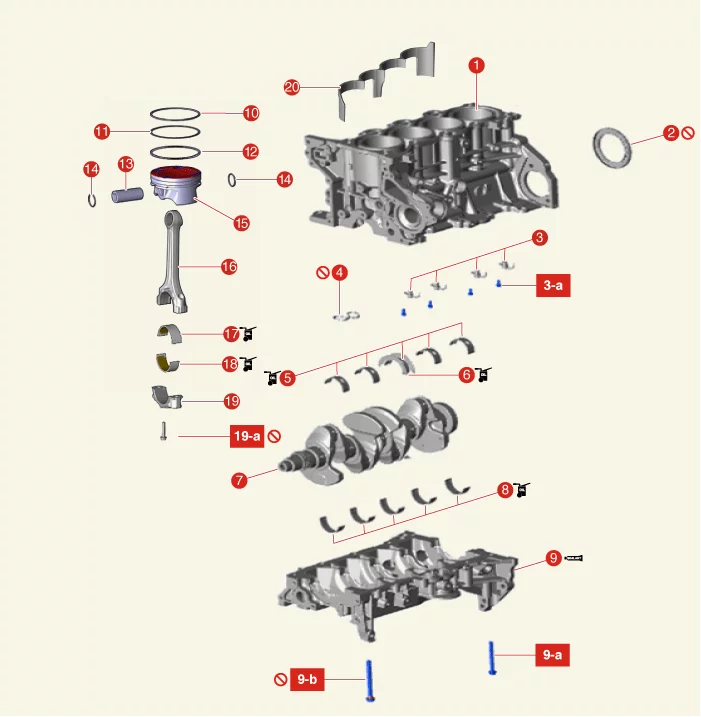
| 1. Cylinder Block 2. Rear Oil Seal 3. Piston Cooling Oil Jet 3-a. 8.8 - 10.8 N·m (0.9 - 1.1 kgf·m, 6.5 - 8.0 lb·ft) 4. Lower Crankcase O-ring 5. Crankshaft Upper Bearing 6. Crankshaft Thrust Bearing 7. Crankshaft |
8. Crankshaft Lower
Bearing 9. Lower Crankcase 9-a. 18.6 - 23.5 N·m (1.9 - 2.4 kgf·m, 13.7 - 17.4 lb·ft) 9-b. 1st step 27.5 - 31.4 N·m (2.8 - 3.2 kgf·m, 20.3 - 23.1 lb·ft) 9-b. 2nd step 120 - 125° 10. Piston Ring (NO.1) 11. Piston Ring (NO.2) |
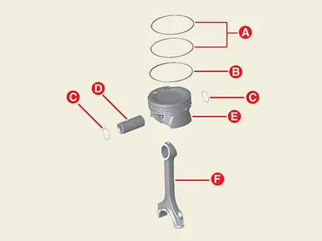
12. Oil ring 13. Piston pin 14. Snap Ring 15. Piston 16. Connecting Rod 17. Connecting Rod Upper Bearing 18. Connecting Rod Lower Bearing 19. Connecting Rod Bearing Cap 19-a. 1st step 17.7 - 21.6 N·m (1.8 - 2.2 kgf·m, 13 - 15.9 lb·ft) 19-a. 2nd step 98 - 102° 20. Water Jacket Insert |
Water Jacket Insert Removal and Installation
| Removal |
| 1. |
Remove the cylinder head assembly.
(Refer to Cylinder Head Assembly - "Cylinder Head")
|
| 2. |
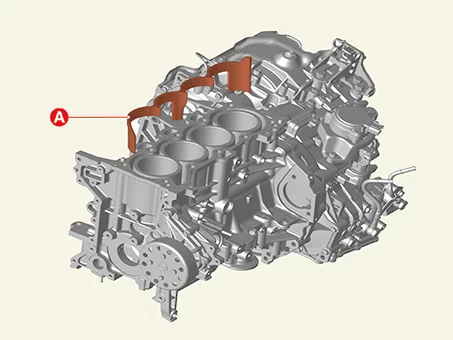
Remove the water jacket insert (A).
|

| Installation |
| 1. |
Install in reverse order of removal.
|
Drive Plate Removal and Installation
| Removal |
| 1. |
Remove the IVT.
(Refer to Intelligent Variable Transmission (IVT) System - "Intelligent
Variable Transmission (IVT)")
|
| 2. |
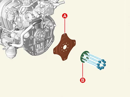
Remove the drive plate (A) and the adapter plate (B) after removing the bolts.
|
| Installation |
| 1. |
Install in the reverse order of removal.
|
Rear Oil Seal Replacement
| Special Service Tool |
|
Tool Name / Number |
Illustration |
Description |
|
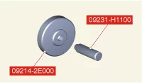
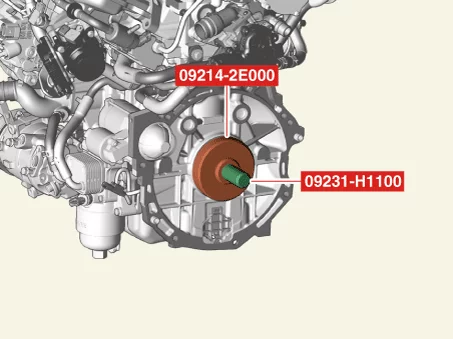
Crankshaft rear oil seal installer 09231 - H1100 09231 - 2E000 |
|
Used for installing crankshaft rear oil seal |
| Replacement |
| 1. |
Remove the drive plate.
(Refer to Cylinder Block - "Drive plate")
|
| 2. |
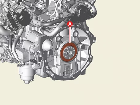
Remove the rear oil seal (A).
|
| 3. |
Install a new rear oil seal.
|
| 4. |
Install in reverse order of removal.
|
Piston and Connecting Rod Disassembly
| Disassembly |
|
|

| 1. |
Remove the engine and transaxle assembly from the vehicle.
(Refer to Engine and Transaxle Assembly - "Engine and Transaxle
Assembly")
|
| 2. |
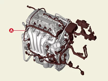
Disconnect the main wiring harness (A) from the engine room.
|
| 3. |
Remove the IVT.
(Refer to Intelligent Variable Transmission (IVT) System - "Intelligent
Variable Transmission (IVT)")
|
| 4. |
Install the engine assembly on the stand.
|
| 5. |
Remove the intake manifold.
(Refer to Intake And Exhaust System - "Intake Manifold")
|
| 6. |
Remove the exhaust manifold.
(Refer to Intake And Exhaust System - "Exhaust Manifold")
|
| 7. |
Remove the water temperature control assembly and heater pipe.
(Refer to Cooling System - "Water Temperature Control Assembly")
|
| 8. |
Remove the compressor
(Refer to Heating,Ventilation And Air Conditioning (Air Conditioner) –
"Compressor")
|
| 9. |
Remove the alternator.
(Refer to Engine Electrical System - "Alternator")
|
| 10. |
Remove the water pump.
(Refer to Cooling System – "Water pump")
|
| 11. |
Remove the cylinder head cover.
(Refer to Cylinder Head Assembly – "Cylinder Head Cover")
|
| 12. |
Remove the timing chain.
(Refer to Timing System – "Timing Chain")
|
| 13. |
Remove the cylinder head assembly.
(Refer to Cylinder Head Assembly - "Cylinder Head")
|
| 14. |
Remove the oil pan.
(Refer to Lubrication - "Oil Pan")
|
| 15. |
Inspect the side clearance of connecting rod.
|
| 16. |
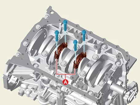
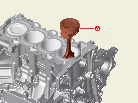
Remove the piston and connecting rod assembly from the cylinder block.
|
| 17. |
Measure the clearance between the piston and piston pin. Try to move the piston back and forth on the
piston pin.
If any movement is felt, replace the piston and piston pin as a set.
|
| 18. |
Remove piston rings.
|
| 19. |
Disassemble the connecting rod from the piston.
|
Piston and Connecting Rod Reassembly
| Reassembly |
|
| 1. |
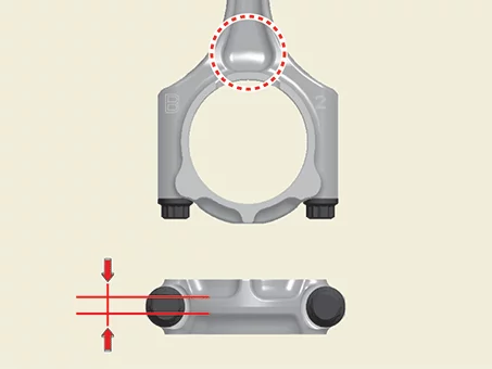
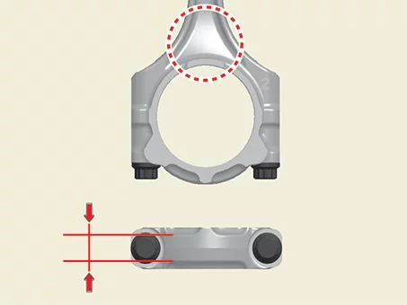
Assemble the piston and the connecting rod.
|

| 2. |
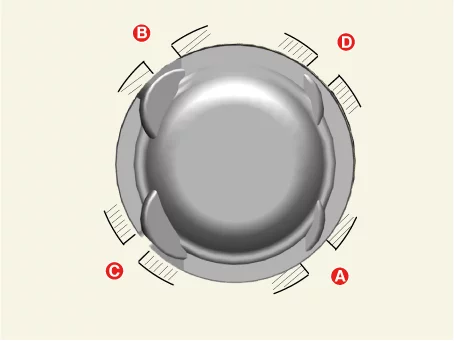
Install the piston ring.
|
| 3. |
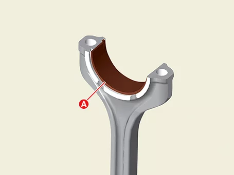
Install the connecting rod bearings.
|
| 4. |
Install the piston and connecting rod assembly.
|
| 5. |
Check the connecting rod end play.
|
| 6. |
Assemble the other parts in the reverse order of disassembly.
|
Piston and Connecting Rod Inspection ➤
Crankshaft Disassembly
| Disassembly |
|
|
| 1. |
Remove the engine and transaxle assembly from the vehicle.
(Refer to Engine and Transaxle Assembly - "Engine and Transaxle
Assembly")
|
| 2. |
Remove the IVT from the engine and transaxle assembly.
(Refer to Intelligent Variable Transmission (IVT) System - "Intelligent
Variable Transmission (IVT)")
|
| 3. |
Install the engine assembly on the stand.
|
| 4. |
Remove the intake manifold.
(Refer to Intake And Exhaust System - "Intake Manifold")
|
| 5. |
Remove the exhaust manifold.
(Refer to Intake And Exhaust System - "Exhaust Manifold")
|
| 6. |
Remove the water temperature control assembly and heater pipe.
(Refer to Cooling System - "Water Temperature Control Assembly")
|
| 7. |
Remove the alternator.
(Refer to Engine Electrical System - "Alternator")
|
| 8. |
Remove the water pump.
(Refer to Cooling System – "Water pump")
|
| 9. |
Remove the cylinder head cover.
(Refer to Cylinder Head Assembly – "Cylinder Head Cover")
|
| 10. |
Remove the timing chain.
(Refer to Timing System – "Timing Chain")
|
| 11. |
Remove the cylinder head assembly.
(Refer to Cylinder Head Assembly - "Cylinder Head")
|
| 12. |
Remove the oil pan and oil screen.
(Refer to Lubrication - "Oil Pan")
|
| 13. |
Remove the piston and connecting rod assembly.
(Refer to Cylinder Block - "Piston and Connecting Rod")
|
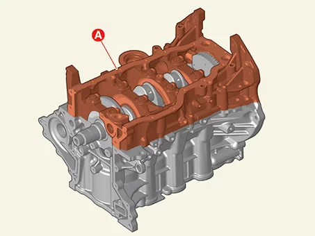
| 14. |
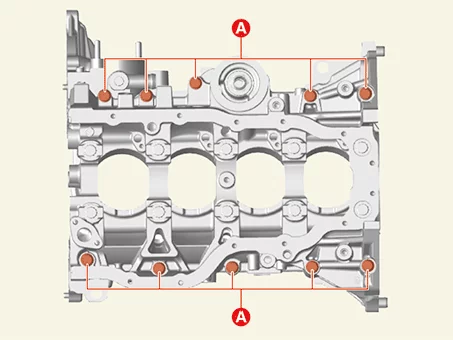
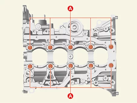
Remove the lower crankcase (A).
|
| 15. |
Check the crankshaft end play.
|
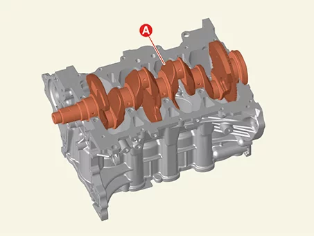
| 16. |
Remove the crankshaft (A) from the cylinder block. At this time, be careful not to damage the crankshaft
journals.
|
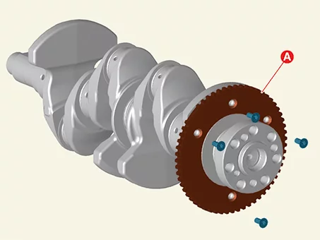
| 17. |
Remove the crankshaft position sensor wheel (A) after removing the bolt.
|
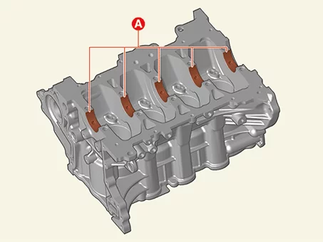
| 18. |
Remove the crankshaft main bearings.
|
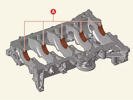
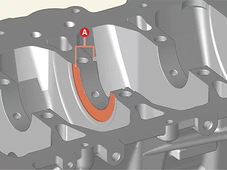
| 19. |
Remove the drive plate.
(Refer to Cylinder Block - "Drive plate")
|
| 20. |
Remove the rear oil seal.
(Refer to Cylinder Block - "Rear Oil Seal")
|
Crankshaft Reassembly
| Reassembly |
|
| 1. |
Install the main bearing.
|
| 2. |
Install the thrust bearings.
Install the two thrust bearings (A) under the cylinder block No. 4 journal with the oil groove facing
outward.
|
| 3. |
Install the crankshaft position sensor wheel (A).
|
| 4. |
Install the crankshaft (A) to the cylinder block.
|
| 5. |
Install the new O-ring (A) to the lower crankcase.
|
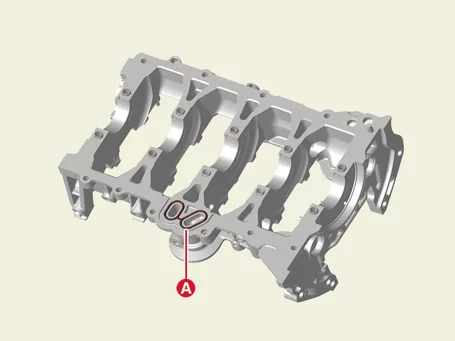
| 6. |
Apply liquid gasket to the lower crankcase mounting surface and then assemble within 5 minutes.
|
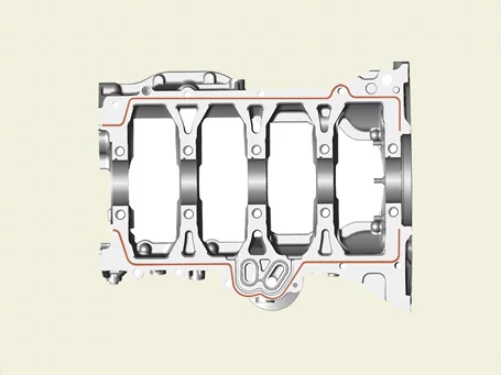
| 7. |
Install the lower crankcase to the cylinder block.
|
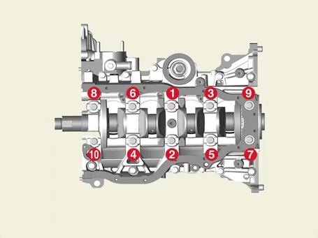
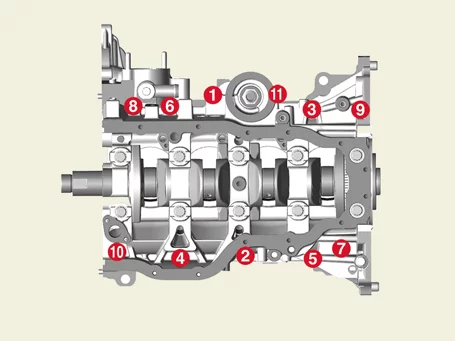
| 8. |
Check the crankshaft end play.
|
| 9. |
Assemble the other parts in the reverse order of disassembly.
|
Crankshaft Inspection
| Inspection |
| 1. |
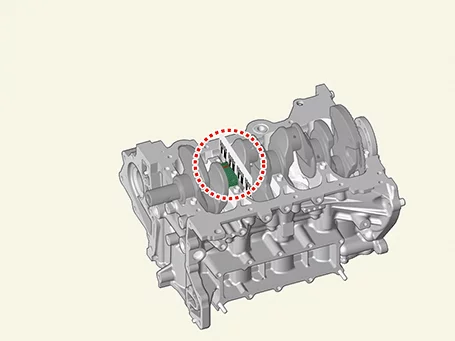
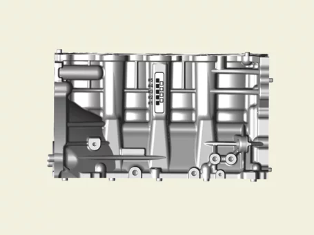
Check the crankshaft bearing oil clearance.
|
|||||||||||||||||||||||||||||||||||||||||||||||||||||||||||||||||||||||||||||||||||||||||||||||||||
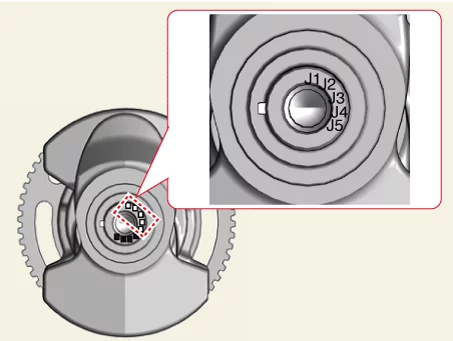
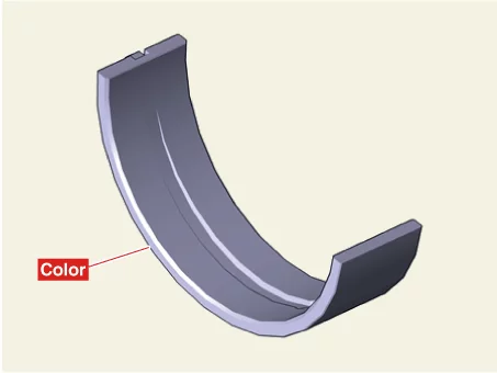
| 2. |
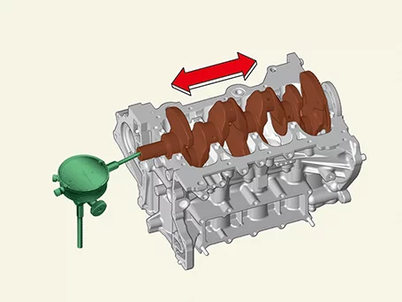
Measure the crankshaft end play.
Check the axial clearance by moving the crankshaft back and forth using a dial gauge.
If end play exceeds limit value, replace the thrust bearing.
|
| 3. |
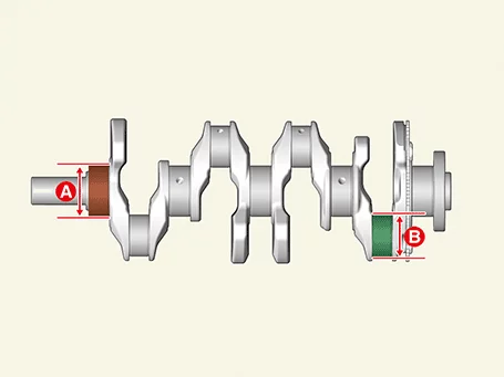
Inspect main journals and crank pins.
Using a micrometer, measure the diameter of each main journal (A) and crank pin (B).
|
Cylinder Block Disassembly
| Disassembly |
|
|
| 1. |
Remove the engine and transaxle assembly from the vehicle.
(Refer to Engine and Transaxle Assembly - "Engine and Transaxle
Assembly")
|
| 2. |
Remove the IVT from the engine and transaxle assembly.
(Refer to Intelligent Variable Transmission (IVT) System - "Intelligent
Variable Transmission (IVT)")
|
| 3. |
Install the engine assembly on the stand.
|
| 4. |
Remove the intake manifold.
(Refer to Intake And Exhaust System - "Intake Manifold")
|
| 5. |
Remove the exhaust manifold.
(Refer to Intake And Exhaust System - "Exhaust Manifold")
|
| 6. |
Remove the water temperature control assembly and heater pipe.
(Refer to Cooling System - "Water Temperature Control Assembly")
|
| 7. |
Remove the alternator.
(Refer to Engine Electrical System - "Alternator")
|
| 8. |
Remove the water pump.
(Refer to Cooling System – "Water pump")
|
| 9. |
Remove the cylinder head cover.
(Refer to Cylinder Head Assembly – "Cylinder Head Cover")
|
| 10. |
Remove the timing chain.
(Refer to Timing System – "Timing Chain")
|
| 11. |
Remove the cylinder head assembly.
(Refer to Cylinder Head Assembly - "Cylinder Head")
|
| 12. |
Remove the oil pan and oil screen.
(Refer to Lubrication - "Oil Pan")
|
| 13. |
Remove the piston and connecting rod assembly.
(Refer to Cylinder Block - "Piston and Connecting Rod")
|
| 14. |
Remove the Crankshaft Position Sensor (CKPS).
(Refer to Engine Control / Fuel System - "Crankshaft Position Sensor
(CKPS)")
|
| 15. |
Remove the crankshaft.
(Refer to Cylinder Block - "Crankshaft")
|
| 16. |
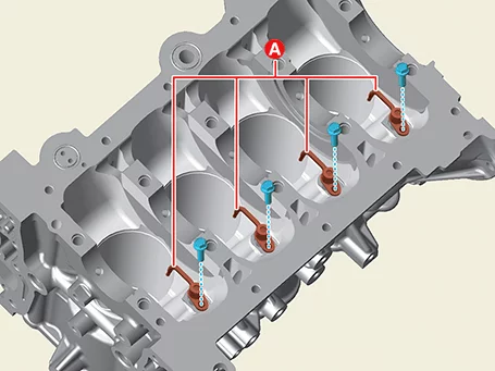
Remove the piston cooling oil jet (A), after removing the bolts.
|
Cylinder Block Reassembly
| Reassembly |
|
| 1. |
Install the piston cooling oil jet (A).
|
| 2. |
Assemble the other parts in the reverse order of disassembly.
|
Cylinder Block Inspection
| Inspection |
| 1. |
Remove the gasket debris on the top of cylinder block using a scraper.
|
| 2. |
Using a soft brush and solvent, thoroughly clean the cylinder block.
|
| 3. |
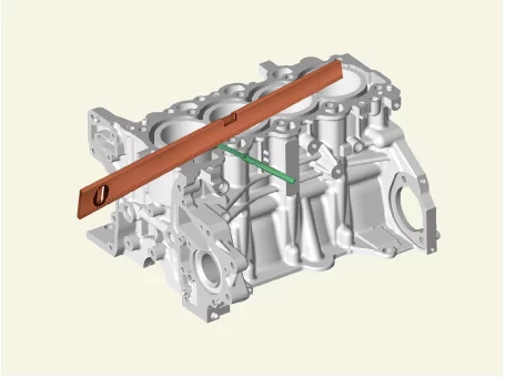
Measure the flatness of the top surface of cylinder block.
Measure the flatness of the surface in contact with the cylinder head gasket using the precise square
ruler and feeler gauge.
|
| 4. |
Visually inspect the inside of cylinder bore for scratches, etc., and replace the cylinder block if
noticeable scratches are found.
|
| 5. |
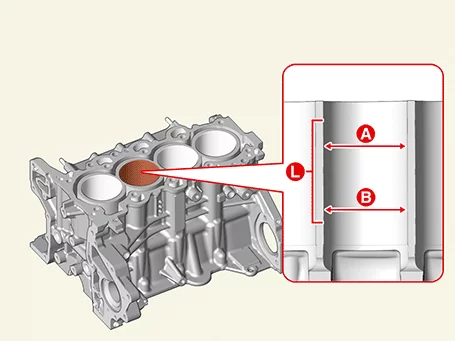
Using a cylinder bore gauge, measure the inner diameter points A and B of the cylinder bore in the axial
and vertical directions.
|


Other information:
Kia Seltos SP2 (2021-2026) Service Manual: How does the air bag system operate?
Air bags in the Kia Seltos are activated and able to inflate only when the ENGINE START/STOP button has been turned to the ON position. The appropriate air bags inflate instantly during a serious frontal collision or side collision to help protect occupants from severe physical injury. There is no single fixed speed at which the air bags will inflate.Kia Seltos SP2 (2021-2026) Service Manual: Rear View Monitor (RVM)
Rear View Monitor (RVM) activates when the back-up light is ON, the ignition switch is ON, and the shift lever is in R (Reverse). RVM is a supplemental function that shows the area behind the Kia Seltos through the infotainment system while backing up. NOTICE After a display audio system or additional genuine Kia infotainment system is installed, Rear View Monitor may not operate exactly as described in the owner's manual.