
Kia Seltos SP2 (2021-2026) Service Manual / All Wheel Drive (AWD) System / Coupling Assembly
Kia Seltos: All Wheel Drive (AWD) System / Coupling Assembly
Contents:
- Direct Electro Hydraulic Actuator Coupling Components and Components Location
- Direct Electro Hydraulic Actuator Coupling Description and Operation
- Direct Electro Hydraulic Actuator Coupling Removal and Installation
- Oil Hydraulic Motor (Actuator) Description and Operation
- Oil Hydraulic Motor (Actuator) On Vehicle Inspection
- Oil Hydraulic Motor (Actuator) Removal
- Oil Hydraulic Motor (Actuator) Installation
- Pressure Sensor Description and Operation
- Pressure Sensor On Vehicle Inspection
- Pressure Sensor Removal and Installation
Direct Electro Hydraulic Actuator Coupling Components and Components Location
| Component Location |
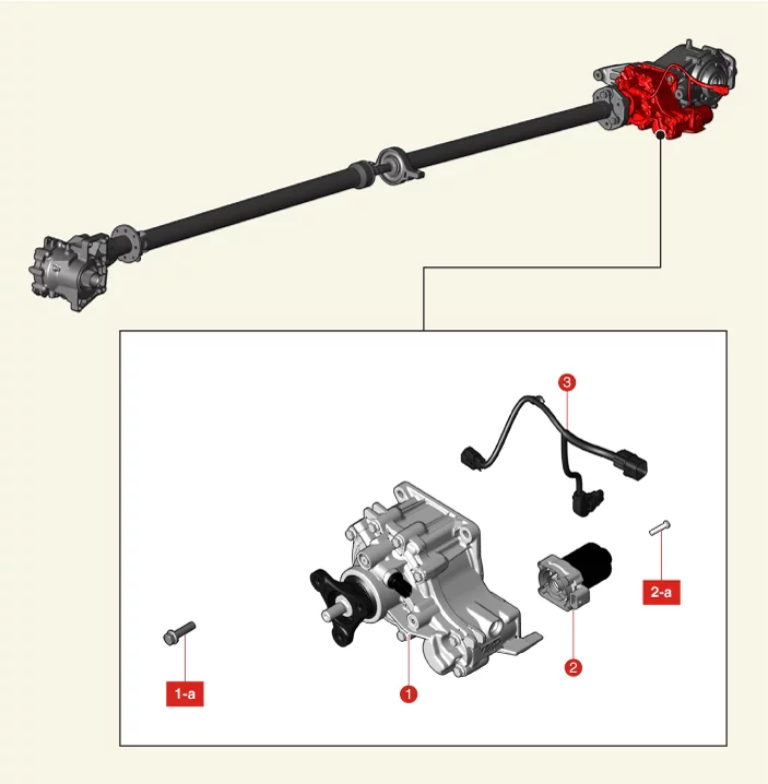
| 1. Direct Electro Hydraulic
Actuator Coupling 1-a. 56.9 - 64.7 N·m (5.8 - 6.6 kgf·m, 42.0 - 47.7 lb·ft) |
2. Oil Hydraulic Motor
(actuator) 2-a. 9.8 - 11.8 N·m (1.0 - 1.2 kgf·m, 7.2 - 8.7 lb·ft) 3. DEHAC Harness |
Direct Electro Hydraulic Actuator Coupling Description and Operation
| Description |
The AWD ECU accurately adjusts the tightening force of the AWD-coupled multi-plate clutch by determining the road
conditions and driving conditions through various sensor signals inputted, thus controlling the magnitude of the
drive transmitted to the rear wheels.
AWD controlling (by Driving condition)
| 1. |
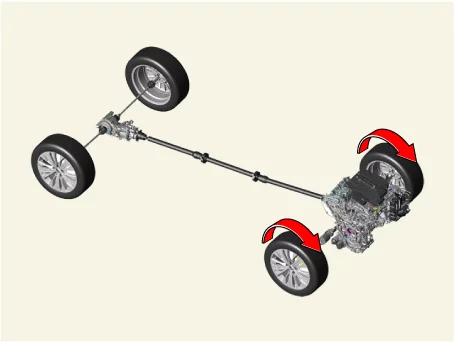
At cruising speed (Automatic mode)
Distribute most of the driving power to front wheels.
|
| 2. |
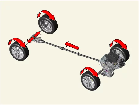
At cornering (Automatic mode)
Distribute driving power to rear wheels according to turning radius and vehicle speed.
|
| 3. |
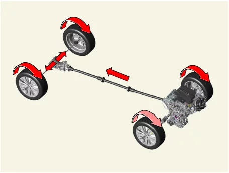
At slip condition (Automatic mode)
When the front wheels slip, the driving power is distributed to the rear wheels depending on the amount
of slip.
|
| 4. |
Terrain mode
Maximize power for a drive through a rough road.
|
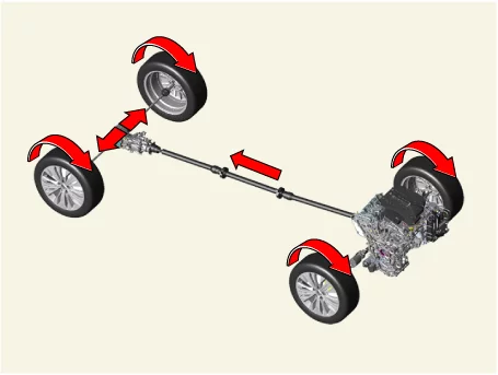
| Operation |
| Direct Electro Hydraulic Actuator Coupling Operation |
[Inactive]
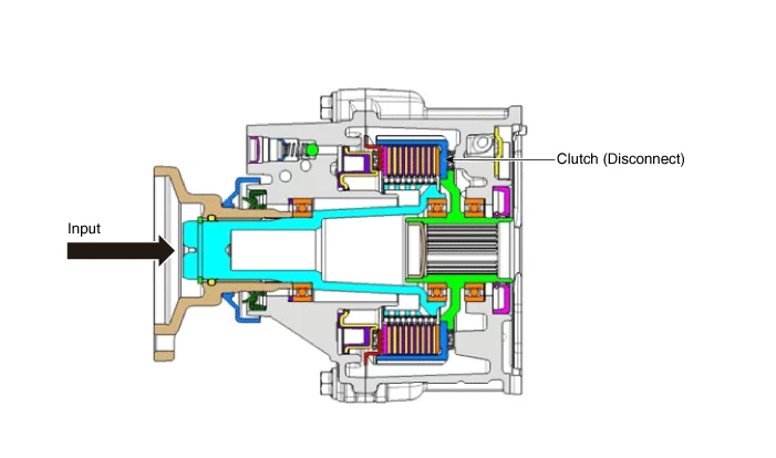
[Active]
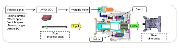
| Operating Sequence 1. AWD ECU receives CAN signals from the vehicle's sensors. 2. AWD ECU calculates the necessary amount of rear-wheel torque and sends the corresponding driving current to the actuator (electronic motor and hydraulic pump). 3. Hydraulic pressure generated by the actuator moves the piston. 4. Friction from the piston's movement engages the clutch. 5. Deliver power to the rear wheels |
Direct Electro Hydraulic Actuator Coupling Removal and Installation
| Removal |
There is no need to check, replenish or replace the coupling assembly oil as it is shipped from the
factory filled with coupling oil. (No maintenance required, lifetime fluid)
|

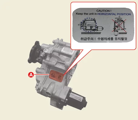
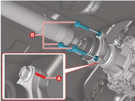
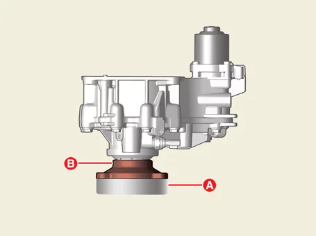
Maintain a horizontal position when removing or installing, or replacing the coupling assembly. (Refer to
caution label (A).)
|

| 1. |
Disconnect the battery negative ( - ) terminal.
|
| 2. |
Remove the propeller shaft assembly.
(Refer to Propeller Shaft Assembly - "Propeller Shaft")
|
| 3. |
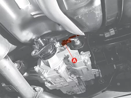
Disconnect the pressure sensor connector (A).
|
| 4. |
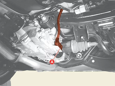
Disconnect the hydraulic motor connector (A).
|
| 5. |
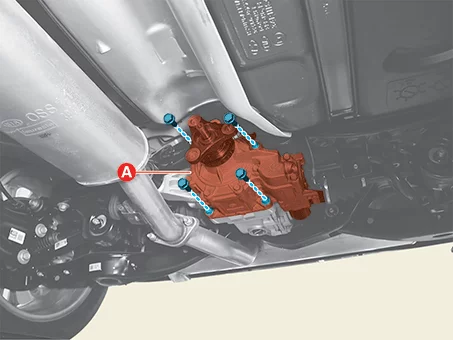
Remove the DEHAC assembly (A) after removing the bolts.
|
| Installation |
| 1. |
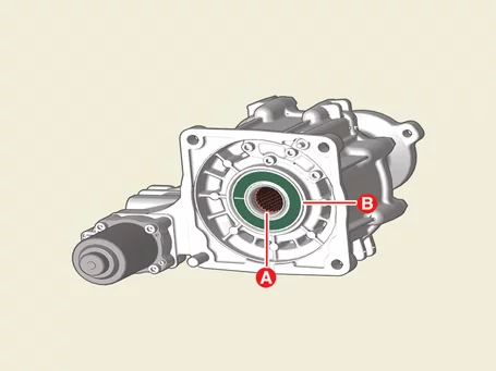
Install in reverse order of removal.
|
| 2. |
Initialize the clutch wear value of the AWE ECU using KDS after replacing the DEHAC assembly.
(Refer to AWD Control System - "Adjustment")
|
Oil Hydraulic Motor (Actuator) Description and Operation
| Description |
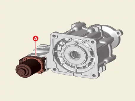
The AWD ECU operates the hydraulic motor(actuator) (A) installed on DEHAC to make hydraulic pressure to press the
multi-disc clutch to supply torque to the rear wheel. the torque varies depending on the degree of compression of
the multi-disc clutch according to the amount of hydraulic pressure.
Oil Hydraulic Motor (Actuator) On Vehicle Inspection
| On Vehicle Inspection |
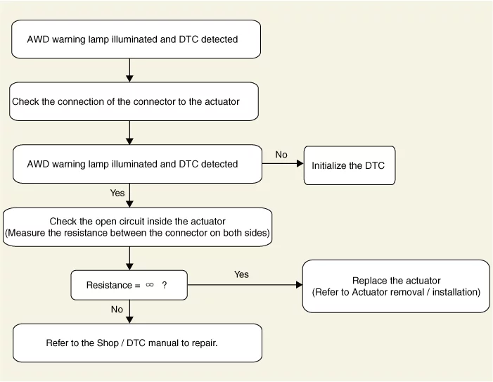
If a DTC code about a hydraulic motor (actuator) is detected, inspect it by following hydraulic motor
inspection procedures.
|
| Hydraulic Motor Inspection Procedures |
Oil Hydraulic Motor (Actuator) Removal
| Removal |
| 1. |
Remove the DEHAC (Direct Electro Hydraulic Actuator Coupling).
(Refer to Coupling Assembly - "Direct Electro Hydraulic Actuator
Coupling" )
|
| 2. |
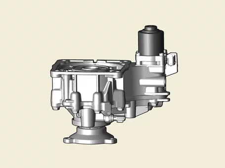
Maintain the removed DEHAC in vertical.
Precautions for Hydraulic Motor Service to Prevent Coupling Oil Leakage (Play ▶)

Notes When Refering Video
This video provides guidance for understanding complex or hard-to-follow procedures by showing each step
clearly.
As needed, the video also provides clear guidance on essential procedural steps, including adjustment
and diagnostic processes, the use of SSTs, and precautions to avoid component damage.
|

| 3. |
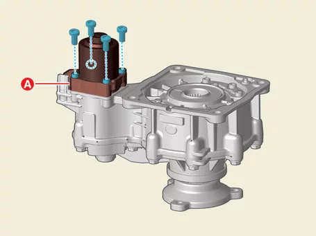
Remove the hydraulic motor (A) after removing the bolts.
|
Oil Hydraulic Motor (Actuator) Installation
| Installation |
| 1. |
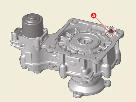
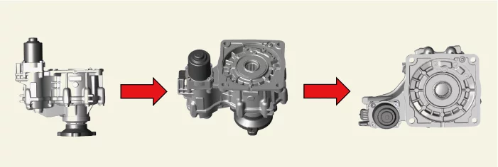
Wipe the foreign materials on the installing surface (A) with a clean cloth.
|
| 2. |
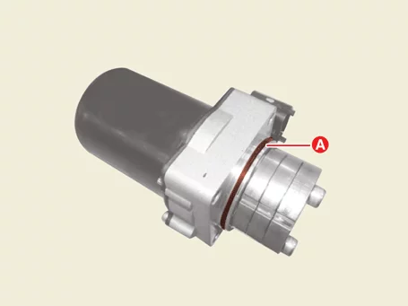
Check the hydraulic motor (actuator) O-ring (A).
|
| 3. |
Install the hydraulic motor (A) and tighten the bolts.
|
| 4. |
Install the DEHAC assembly.
(Refer to Coupling Assembly - "Direct Electro Hydraulic Actuator
Coupling" )
|
Pressure Sensor Description and Operation
| Description |
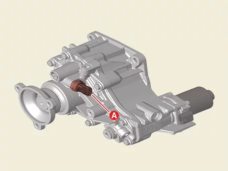
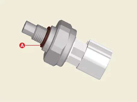
The AWD ECU receives pressure values from the pressure sensor (A) mounted on the electronically controlled
hydraulic coupling and controls the motor pump so that the target hydraulic pressure corresponding to the rear wheel
distribution torque to be controlled is generated.
Pressure Sensor On Vehicle Inspection
| On Vehicle Inspection |
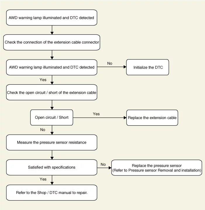
If a DTC code about a pressure sensor is detected, inspect it by following pressure sensor inspection
procedures.
|
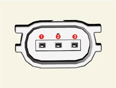
| Pressure Sensor Inspection Procedures |
| Pressure Sensor Resistance Measurement |
| 1. |
Disconnect the battery negative ( - ) terminal.
|
| 2. |
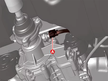
Disconnect the pressure sensor connector (A).
|
| 3. |
Measure the resistance between the pressure sensor pins.
|
| 4. |
Check the resistance values measured in accordance with Table 1.
[Table 1]
|
Pressure Sensor Removal and Installation
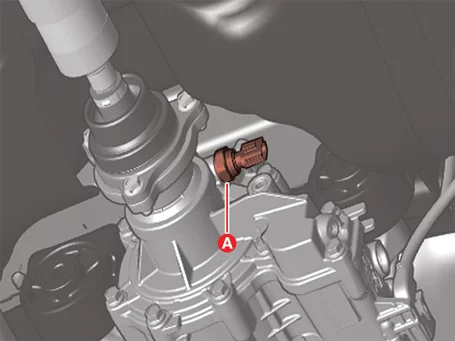
| Removal |
| 1. |
Disconnect the battery negative ( - ) terminal.
|
| 2. |
Disconnect the pressure sensor connector (A).
|
| 3. |
Remove the pressure sensor (A).
|
| Installation |
|
| 1. |
Install in reverse order of removal.
|


Other information:
Kia Seltos SP2 (2021-2026) Service Manual: Windshield defrosting and defogging
When the Kia Seltos windshield is covered with frost, fog, or moisture, the front view may become blurred. Remove frost and moisture before driving to maintain clear visibility and safer vehicle control. WARNING Windshield heating Do not use the or position during cooling operation in extremely humid weather. The temperature difference between the outside air and the windshield may cause the outer surface of the windshield to fog, reducing visibility.Kia Seltos SP2 (2021-2026) Service Manual: Tire terminology and definitions
Refer to the following definitions for tire-related terms commonly found in the Kia Seltos tire description, tire placard, sidewall markings, and maintenance information. Air Pressure: The amount of air inside the tire pressing outward against the tire structure. Air pressure is measured in pounds per square inch (psi) or kilopascals (kPa). Accessory Weight: The combined weight of optional accessories installed on the vehicle.