Contents:
Components and Components Location
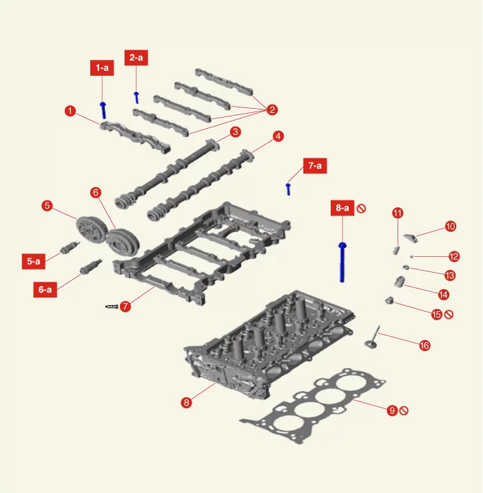
1. Camshaft Front Bearing
Cap
1-a. 1st step M8 bolt 9.8 - 11.8 N·m (1.0 - 1.2 kgf·m, 7.2 - 8.7 lb·ft)
1-a. 2nd step M8 bolt 18.6 -
22.6 N·m (1.9 - 2.3 kgf·m, 13.7 - 16.6 lb·ft)
1-a. 1st step M6 bolt 4.9 - 7.8 N·m (0.5 - 0.8 kgf·m, 3.6 -
5.8 lb·ft, 43.4 - 69.4 lb·in)
1-a. 2nd step M6 bolt 11.8 - 13.7 N·m (1.2 - 1.4 kgf·m, 8.7 - 10.1
lb·ft)
2. Camshaft bearing cap
2-a. 1st step M8 bolt 9.8 - 11.8 N·m (1.0 - 1.2 kgf·m, 7.2 - 8.7
lb·ft)
2-a. 2nd step M8 bolt 18.6 - 22.6 N·m (1.9 - 2.3 kgf·m, 13.7 - 16.6 lb·ft)
2-a. 1st step M6 bolt
4.9 - 7.8 N·m (0.5 - 0.8 kgf·m, 3.6 - 5.8 lb·ft, 43.4 - 69.4 lb·in)
2-a. 2nd step M6 bolt 11.8 - 13.7 N·m
(1.2 - 1.4 kgf·m, 8.7 - 10.1 lb·ft)
3. Exhaust Camshaft
4. Intake Camshaft
5. Exhaust CVVT
Assembly
5-a. 64.7 - 76.5 N·m (6.6 - 7.8 kgf·m, 47.7 - 56.4 lb·ft)
6. Intake CVVT Assembly
6-a. 64.7
- 76.5 N·m (6.6 - 7.8 kgf·m, 47.7 - 56.4 lb·ft)
|
7. Cam Carrier
7-a. 18.6 -
22.6 N·m (1.9 - 2.3 kgf·m, 13.7 - 16.6 lb·ft)
8. Cylinder Head
8-a. 1st step 32.4 - 36.3 N·m (3.3 - 3.7
kgf·m, 23.9 - 26.8 lb·ft)
8-a. 2nd step 90 - 95°
8-a. 3rd step 90 - 95°
9. Cylinder Head
Gasket
10. Swing Arm
11. Hydraulic Lash Adjuster (HLA)
12. Valve Retainer
13. Valve Retainer
Lock
14. Valve spring
15. Valve stem seal
16. Valve
|
Cylinder Head Cover Components and Components Location
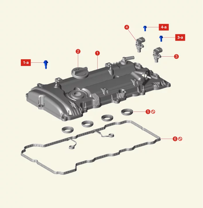
1. Cylinder Head Cover
1-a. 1st step 3.9 - 5.9 N·m
(0.4 - 0.6 kgf·m, 2.9 - 4.3 lb·ft)
1-a. 2nd step 7.8 - 9.8 N·m (0.8 - 1.0 kgf·m, 5.8 - 7.2 lb·ft)
2. Oil
Filler Cap
3. Camshaft Position Sensor (CMPS) -Intake
3-a. 9.8 - 11.8 N·m (1.0 - 1.2 kgf·m, 7.2 - 8.7
lb·ft)
|
4. Camshaft Position Sensor (CMPS) -Exhaust
4-a.
9.8 - 11.8 N·m (1.0 - 1.2 kgf·m, 7.2 - 8.7 lb·ft)
5. Oil Seal
6. Cylinder Head Cover Gasket
|
Cylinder Head Cover Removal
|
•
|
Use a fender cover to protect the painted surface.
|
|
•
|
Be careful not to damage the connector when disconnecting.
|
|
|
•
|
Mark wiring and hoses to prevent incorrect connections.
|
|
| 1. |
Disconnect the battery negative ( - ) terminal.
|
| 2. |
Remove the engine cover.
(Refer to Engine and Transaxle Assembly - "Engine Cover")
|
| 3. |
Remove the air duct and air cleaner assembly.
(Refer to Intake and Exhaust System - "Air Cleaner")
|
| 4. |
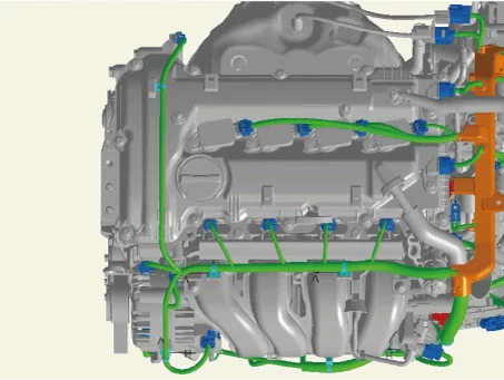
Disconnect the engine wiring connector and harness clamp around the cylinder head cover and remove the
connector bracket.
|
| 5. |
Remove the ignition coil.
(Refer to Engine Electrical System - "Ignition Coil")
|
| 6. |
Remove the oil level gauge.
(Refer to Lubrication System - "Oil Level Gauge & Pipe")
|
| 7. |
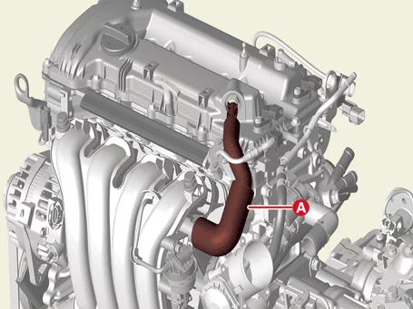
Separate the PCV hose (A) by releasing the clamp.
|
| 8. |
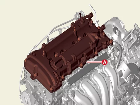
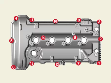
Remove the cylinder head cover (A), after removing the bolt.
|
Remove the bolts following the below orders.
|
|
Cylinder Head Cover Installation
| 1. |
Install the cylinder head cover.
| (1)
|
Remove the hardened sealant, foreign matter, and oil from the cylinder head cover, timing chain
cover, and upper surface of the cam carrier.
|
| (2)
|
Apply engine oil on the lip portion of the oil seal on the cover and outer surface of the spark
plug pipes.
|
| (3)
|
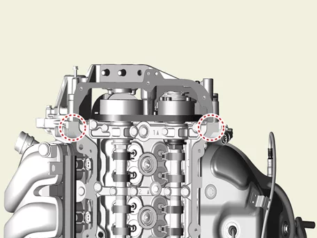
Assemble within 5 minutes of applying sealant on the gap between the timing chain cover and the
cam carrier.
Bead width : 2.0 - 3.0 mm (0.08 - 0.12 in.)
Sealant : Threebond 1217H or equivalent
|
|
| (4)
|
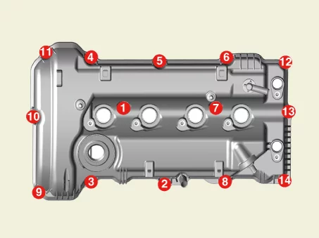
Install the cylinder head cover in the sequence shown.
Tightening torque
1st step : 3.9 - 5.9 N·m (0.4 - 0.6 kgf·m, 2.9 - 4.3 lb·ft)
2nd step : 7.8 - 9.8 N·m (0.8 - 1.0 kgf·m, 5.8 - 7.2 lb·ft)
|
|
|
•
|
Do not reuse cylinder head cover gasket.
|
|
•
|
Check whether the gasket gets out from the cylinder head cover, before installing the
cylinder head cover.
|
|
•
|
Do not operate the engine or pressurize the inside of the engine before 30 minutes after
assembling the cylinder head cover.
|
|
|
| 2. |
Assemble the other parts in the reverse order of disassembly.
|
CVVT & Camshaft Description and Operation
Continuous Variable Valve Timing (CVVT) system advances or retards the valve timing of the intake and exhaust
valve in accordance with the ECM control signal which is calculated by the engine speed and load.
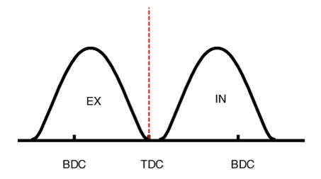
By controlling CVVT, the valve over-lap or under-lap occurs, which makes better fuel economy and reduces exhaust
gases (NOx, HC) and improves engine performance through reduction of pumping loss, internal EGR effect, improvement
of combustion stability, improvement of volumetric efficiency, and increase of expansion work.
This system consist of
|
–
|
the CVVT Oil Control Valve (OCV) which supplies the engine oil to the cam phaser or runs out the engine
oil from the cam phaser in accordance with the ECM PWM (Pulse With Modulation) control signal,
|
|
–
|
and the Cam Phaser which varies the cam phase by using the hydraulic force of the engine oil.
|
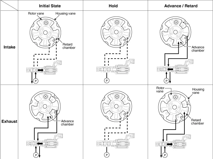
The engine oil getting out of the CVVT oil control valve varies the cam phase in the direction (Intake
Advance/Exhaust Retard) or opposite direction (Intake Retard/Exhaust Advance) of the engine rotation by rotating the
rotor connected with the camshaft inside the cam phaser.
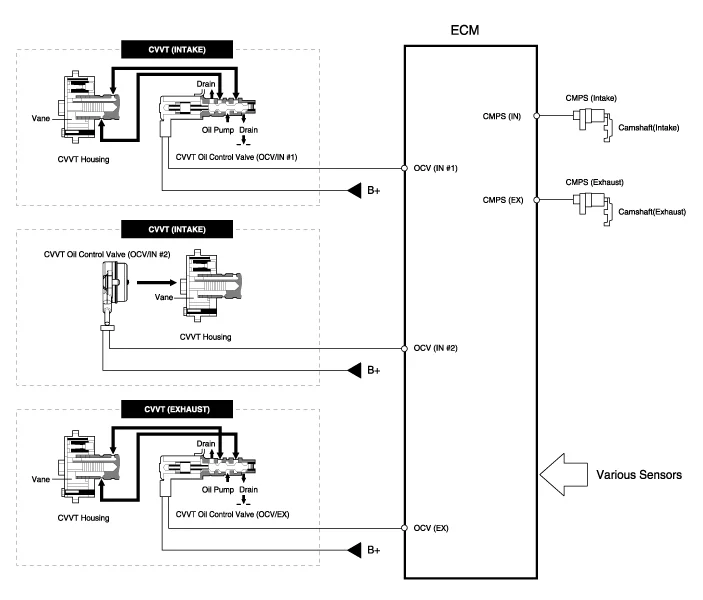
The CVVT system operates in a structure of rotating the rotor vane by hydraulic pressure by supplying oil to the
advance chamber or the retard chamber through flow path control of the CVVT oil control valve (OCV).
|
On the intake side, a separate solenoid valve for locking and releasing a separate lock pin is mounted on
the chain cover.
|
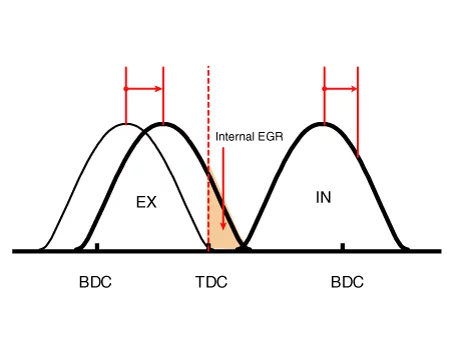
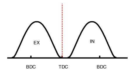
[CVVT System Mode]
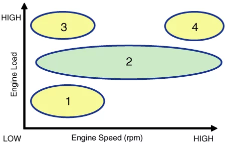
(1) Low Speed/Low Load
|
(2) Partial Load
|
|
|
|
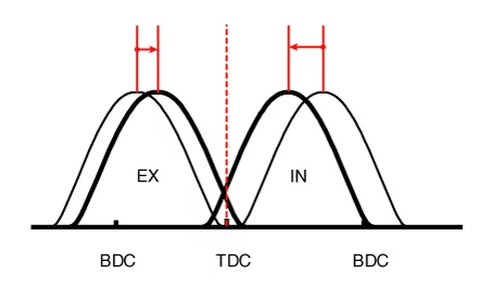
(3) Low Speed/High Load
|
(4) High Speed/High Load
|
|
|
|
Driving Condition
|
Exhaust valve
|
Intake valve
|
Valve timing
|
Improves
|
Valve timing
|
Improves
|
(1) Low Speed/Low Load
|
Completely Advance
|
*Valve Under-lap
*Improvement of combustion stability
|
Middle
|
*Valve Under-lap
*Improvement of combustion stability
|
(2) Partial Load
|
Retard
|
*Reduction of HC
|
Retard
|
*Reduction of pumping loss
|
(3) Low Speed/High Load
|
Completely Advance
|
* Reduction of pumping loss
|
Advance
|
* Volume efficiency improvement
|
(4) High Speed/High Load
|
Completely Advance
|
* Reduction of pumping loss
|
Advance
|
* Volume efficiency improvement
|
CVVT & Camshaft Removal
|
•
|
Use a fender cover to protect the painted surface.
|
|
•
|
Be careful not to damage the connector when disconnecting.
|
|
|
•
|
Mark wiring and hoses to prevent incorrect connections.
|
|
•
|
Rotate the crankshaft to place the no.1 cylinder piston at the compress TDC.
|
|
| 1. |
Disconnect the battery negative (-) terminal.
(Refer to Engine Electrical System - "Battery")
|
| 2. |
Remove the intake middle lock control solenoid.
(Refer to Engine Control / Fuel System - "Intake Middle Lock Control
Solenoid")
|
| 3. |
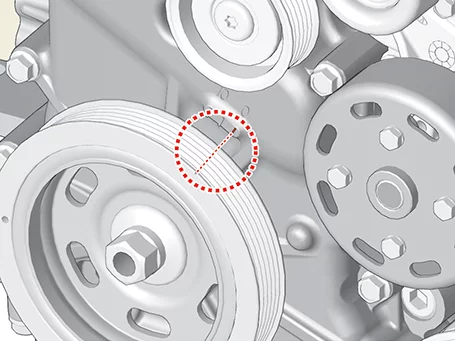
Turn the crankshaft damper pulley clockwise to bring the piston of cylinder 1 to compression top dead
center so that the timing mark on the timing chain cover matches the groove on the damper pulley.
|
| 4. |
Remove the timing chain.
(Refer to Timing System - "Timing Chain")
|
Do not reuse the timing chain tensioner.
|
|
| 5. |
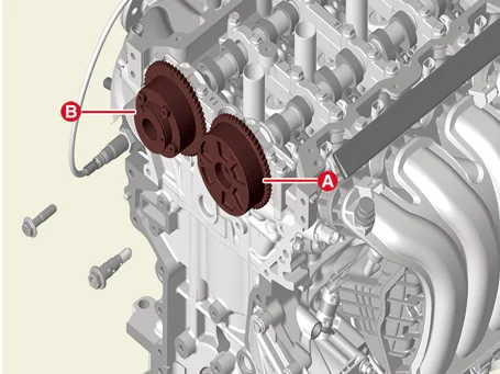
Remove the intake CVVT assembly (A) and exhaust CVVT assembly (B).
Tightening torque : 64.7 - 76.5 N·m (6.6 - 7.8 kgf·m, 47.7
- 56.4 lb·ft)
|
|
•
|
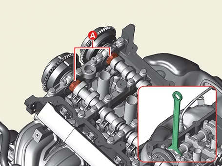
When removing the OCV and center bolt, fix the camshaft hexagon part (A) with a wrench so
that it does not rotate.
|
|
•
|
Be careful not to get contaminant into the OCV and center bolt.
|
|
|
| 6. |
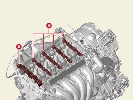
Remove camshaft front bearing cap (A) and camshaft bearing cap (B) after removing bolts.
Tightening torque
1st step
M8 bolts : 9.8 - 11.8 N·m (1.0 - 1.2 kgf·m, 7.2 - 8.7 lb·ft)
M6 bolts : 4.9 - 7.8 N·m (0.5 - 0.8 kgf·m, 3.6 - 5.8 lb·ft, 43.4 - 69.4 lb·in)
2nd step
M8 bolts : 18.6 - 22.6 N·m (1.9 - 2.3 kgf·m, 13.7 - 16.6 lb·ft)
M6 bolts : 11.8 - 13.7 N·m (1.2 - 1.4 kgf·m, 8.7 - 10.1 lb·ft)
|
|
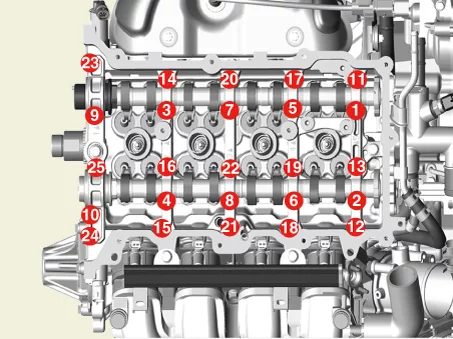
Install the camshaft front bearing cap and camshaft bearing caps in the sequence shown.
|
|
| 7. |
Remove the intake and exhaust camshaft (A).
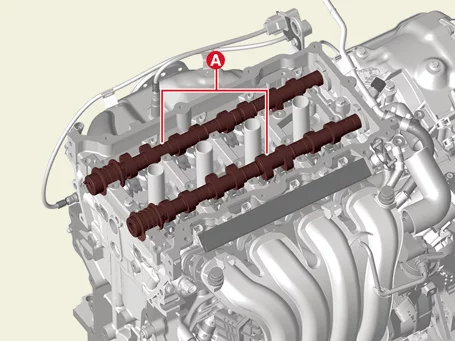
|
CVVT & Camshaft Installation
|
Do not reuse the timing chain tensioner.
|
| 1. |
Install the camshaft.
| (1)
|
Install the intake and exhaust camshaft (A).
|
| (2)
|
Install the camshaft front bearing cap and camshaft bearing cap in the order shown.
Tightening torque
1st step
M8 bolts : 9.8 - 11.8 N·m (1.0 - 1.2 kgf·m, 7.2 - 8.7 lb·ft)
M6 bolts : 4.9 - 7.8 N·m (0.5 - 0.8 kgf·m, 3.6 - 5.8 lb·ft, 43.4 - 69.4 lb·in)
2nd step
M8 bolst : 18.6 - 22.6 N·m (1.9 - 2.3 kgf·m, 13.7 - 16.6 lb·ft)
M6 bolts : 11.8 - 13.7 N·m (1.2 - 1.4 kgf·m, 8.7 - 10.1 lb·ft)
|
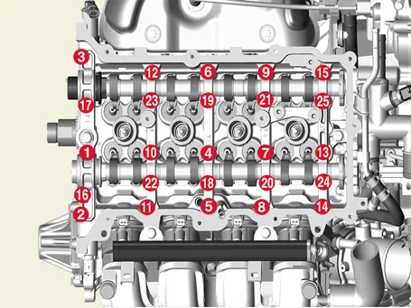
|
|
| 2. |
Install the intake CVVT assembly (A) and exhaust CVVT assembly (B).
|
•
|
When installing the OCV and center bolt, fix the camshaft hexagon part (A) with a wrench
so that it does not rotate.
|
|
•
|
Do not reuse intake/exhaust CVVT OCV bolts.
|
|
|
| 3. |
Install in reverse order of removal.
|
•
|
Install to the specified torque.
|
|
•
|
Do not reuse the timing chain tensioner.
|
|
|
CVVT & Camshaft Inspection
Camshaft
| 1. |
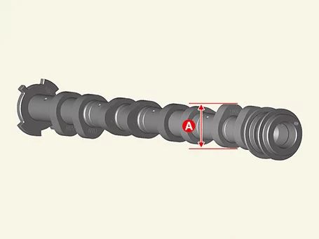
Check cam height.
Using a micrometer, measure the cam lobe height.
Check the cam lobe surface for abnormal wear and damage and replace if necessary.
Cam height
Intake : 39.0 mm (1.5354 in.)
Exhaust : 38.66 mm (1.5220 in.)
|
|
| 2. |
Check the camshaft journal for wear and replace the camshaft if the journal is badly damaged.
|
| 3. |
Inspect the camshaft journal clearance.
| (1)
|
Clean the bearing caps and camshaft journals.
|
| (2)
|
Place the camshafts on the cylinder head.
|
| (3)
|
Lay a strip of plastic gauge across each of the camshaft journal.
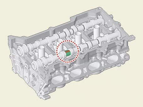
|
| (4)
|
Install the camshaft front bearing cap and camshaft bearing caps in the sequence below.
Tightening torque
1st step
M8 bolts : 9.8 - 11.8 N·m (1.0 - 1.2 kgf·m, 7.2 - 8.7 lb·ft)
M6 bolts : 4.9 - 7.8 N·m (0.5 - 0.8 kgf·m, 3.6 - 5.8 lb·ft, 43.4 - 69.4 lb·in)
2nd step
M8 bolst : 18.6 - 22.6 N·m (1.9 - 2.3 kgf·m, 13.7 - 16.6 lb·ft)
M6 bolts : 11.8 - 13.7 N·m (1.2 - 1.4 kgf·m, 8.7 - 10.1 lb·ft)
|
|
•
|
Do not turn the camshaft.
|
|
|
| (5)
|
Remove the bearing caps.
|
| (6)
|
Measure the plastic gauge at its widest point.
If the oil clearance exceeds the specified value, replace the camshaft. If necessary, replace the
bearing cap and cam carrier.
Camshaft bearing oil clearance
Standard :
0.032 - 0.062 mm (0.0013 - 0.0024 in.)
|
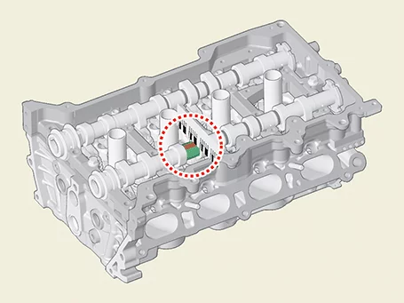
|
|
| 4. |
Inspect the camshaft end play.
| (1)
|
Install the camshaft bearing caps.
|
| (2)
|
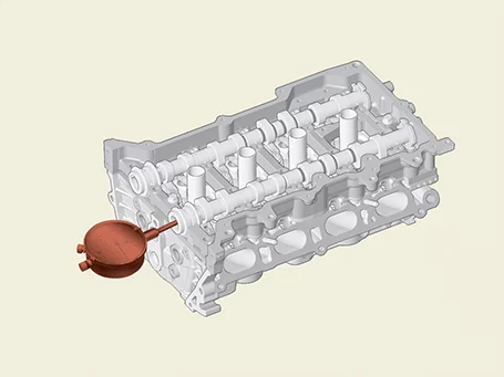
Use a dial gauge to measure the end play while moving the camshaft in the axial direction.
If the end play exceeds the limit, replace the camshaft.
Replace bearingcap and cam carrier if necessary.
Camshaft end play
Standard :
0.10 - 0.19 mm (0.0039 - 0.0075 in.)
|
|
|
Cylinder Head Removal
|
•
|
Use a fender cover to protect the painted surface.
|
|
•
|
Wait for the engine to cool to room temperature before disassembling to prevent damage to the
cylinder head.
|
|
•
|
When handling a metal gasket, take care not to fold the gasket or damage the contact surface of
the gasket.
|
|
•
|
To avoid damage, disconnect the wiring connectors carefully.
|
|
|
•
|
Mark wiring and hoses to prevent incorrect connections.
|
|
•
|
Rotate the crankshaft to place the no.1 cylinder piston at the compress TDC.
|
|
| 1. |
Release the residual pressure in fuel line.
(Refer to Fuel Delivery System - "Release Residual Pressure in Fuel
Line")
|
| 2. |
Disconnect the battery negative ( - ) terminal.
|
| 3. |
Remove the engine cover.
(Refer to Engine and Transaxle Assembly - "Engine Cover")
|
| 4. |
Remove the air duct and air cleaner assembly.
(Refer to Intake and Exhaust System - "Air Cleaner")
|
| 5. |
Remove the battery and battery tray.
(Refer to Engine Electrical System - "Battery")
|
| 7. |
Remove the Engine Control Module (ECM).
(Refer to Engine Control / Fuel System - "Engine Control Module
(ECM)")
|
| 8. |
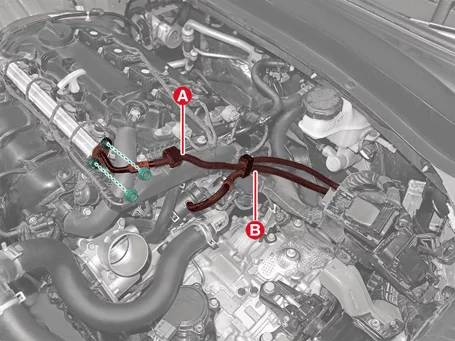
Disconnect the fuel hose (A) and Purge Control Solenoid Valve (PCSV) hose (B) after removing nuts.
Tightening torque :
8.8 - 11.8 N·m (0.9 - 1.2 kgf·m, 6.5 - 8.7 lb·ft)
|
|
| 9. |
Remove the delivery pipe.
(Refer to Engine Control / Fuel System - "Delivery Pipe")
|
| 10. |
Remove the cylinder head cover.
(Refer to Cylinder Head Assembly - "Cylinder Head Cover")
|
| 11. |
Remove the intake manifold.
(Refer to Intake and Exhaust System - "Intake Manifold")
|
| 12. |
Remove the exhaust manifold.
(Refer to Intake And Exhaust System - "Exhaust Manifold")
|
| 13. |
Remove the water temperature control assembly.
(Refer to Cooling System -"Water Temperature Control Assembly")
|
| 14. |
Remove the timing chain.
(Refer to Timing System - "Timing Chain Cover")
|
| 15. |
Remove the intake CVVT assembly and exhaust CVVT assembly.
(Refer to Cylinder Head Assembly - "CVVT & Camshaft")
|
| 16. |
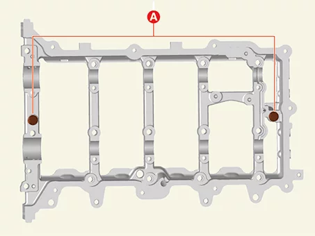
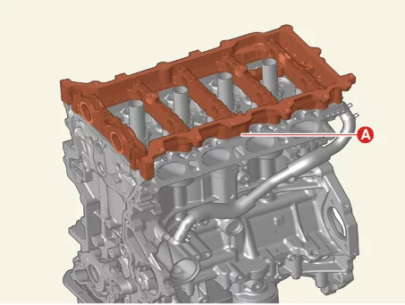
Remove the cam carrier (A).
| (1)
|
Remove the cam carrier bolts (A).
Tightening torque :
18.6 - 22.6 N·m (1.9 - 2.3 kgf·m, 13.7 - 16.6 lb·ft)
|
|
| (2)
|
Remove the cam carrier (A).
|
|
| 17. |
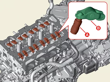
Remove the hydraulic valve clearance adjuster (HLA) (A) and swing arm (B).
|
| 18. |
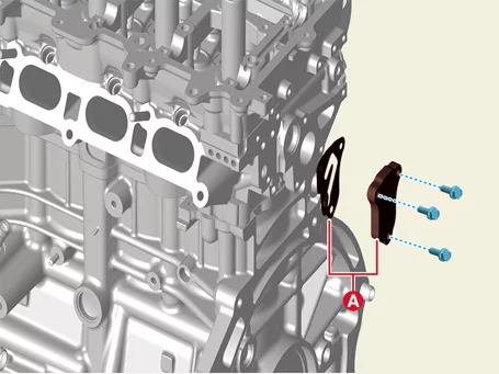
Remove the oil control adapter with the gasket (A) after removing bolts.
Tightening torque :
9.8 - 11.8 N·m (1.0 - 1.2 kgf·m, 7.2 - 8.7 lb·ft)
|
|
| 19. |
Remove the CVVT Oil Control Valve (OCV).
(Refer to Engine Control / Fuel System - "CVVT Oil Control Valve
(OCV)")
|
| 20. |
Remove the spark plug.
(Refer to Engine Electrical System - "Spark Plug")
|
| 21. |
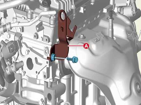
Remove the rear engine hanger (A) after removing the bolt.
Tightening torque :
34.3 - 39.2 N·m (3.5 - 4.0 kgf·m, 25.3 - 28.9 lb·ft)
|
|
| 22. |
Remove the cylinder head after removing the bolts.
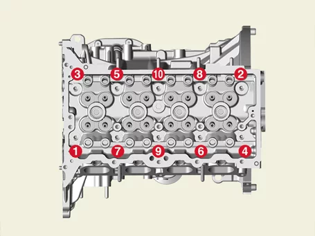
| (1)
|
Loosen the head bolt by dividing 2 - 3 times as below the order in figure.
Tightening torque
1st step : 32.4 - 36.3 N·m (3.3 - 3.7 kgf·m, 23.9 - 26.8 lb·ft)
2nd step : 90 - 95°
3rd step : 90 - 95°
|
|
If the cylinder head bolts are loosened in the wrong order, it may deformed.
|
|
| (2)
|
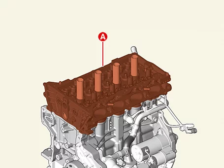
Lift the cylinder head (A) from the cylinder block and put it on a wooden block.
|
Be careful not to damage the contact surfaces of the cylinder head and cylinder block.
|
|
| (3)
|
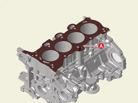
Remove the cylinder head gasket (A).
|
|
Cylinder Head Installation
Tool Name / Number
|
Illustration
|
Description
|
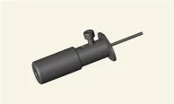
HLA air bleed tool
0K246 - L8000
|
|
Used to air bleed HLA
|
|
•
|
Clean the parts to install.
|
|
•
|
Do not reuse cylinder head gasket and manifold gasket.
|
|
•
|
Do not reuse cylinder head bolts.
|
|
•
|
The cylinder head gasket is made of metal, so be careful not to bend it.
|
|
•
|
Rotate the crankshaft to place the No.1 cylinder piston at the at the TDC.
|
|
| 1. |
Install the cylinder head.
| (1)
|
Clean the cylinder head and gasket contact surface of the cylinder block so that foreign objects
are not on it like oil, dirt, etc.
|
| (2)
|
Apply liquid gasket on the top of the cylinder block.
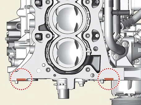
|
| (3)
|
Install the cylinder head gasket (A).
|
| (4)
|
Apply liquid sealant on the top of the cylinder head gasket.
Bead width : 3.500 - 4.500 mm (0.14 - 0.18 in.)
Sealant : Threebond 1217H or equivalent
|
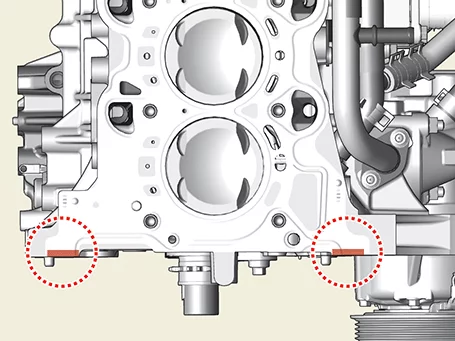
|
Assemble the cylinder head gasket and cylinder head within 5 minutes after applying the
liquid sealant.
|
|
|
| 2. |
Install the cylinder head (A) slowly to prevent damage to the head gasket.
|
| 3. |
Install new cylinder head bolts.
Tightening torque
1st step : 32.4 - 36.3 N·m (3.3 - 3.7 kgf·m, 23.9 - 26.8 lb·ft)
2nd step : 90 - 95°
3rd step : 90 - 95°
|
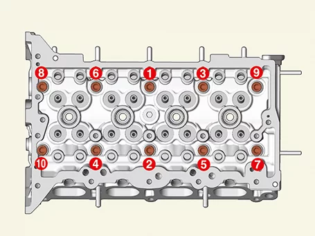
|
•
|
Do not reuse cylinder head bolts.
|
|
•
|
Do not apply the engine oil to the new bolt of the cylinder head.
|
|
•
|
Remove the protruding sealants within 5 minutes after assembling the cylinder head bolts.
|
|
•
|
The engine running or pressure test should not be performed within 30 minutes after
assembling the cylinder head.
|
|
•
|
When installing the cylinder head bolts, distinguish the vertical direction of the
cylinder head bolt washers to ensure that the round and chamber parts are facing the
cylinder head bolt head.
|
|
|
| 4. |
Install the spark plug.
(Refer to Engine Electrical System - "Spark Plug")
|
| 5. |
Perform the HLA air bleding.
| (1)
|
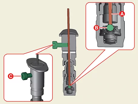
Remove the cover (A) of the special tool (0K246 - L8000) and loosen the bolt (B).
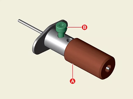
|
Do not remove the bolt (B).
|
|
| (2)
|
Tighten the bolt (C) with the special tool (0K246 - L8000) with the pin (A) on the ball (B).
|
Be careful not to push down the pin (A) too hard as the weight of the ball is only a few
grams (g).
|
|
| (3)
|
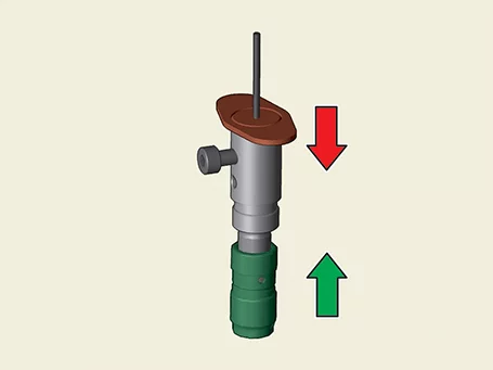
Hold HLA and special tool (0K246 - L8000) in oil with your hand and press it 4-5 times in the
direction of the arrow.
|
| (4)
|
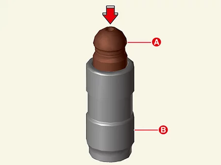
Hold the bottom (B) of the HLA filled with engine oil and press the cap (A) with your hands,
repeating procedure 3 until the cap (A) is not pressed.
|
|
| 6. |
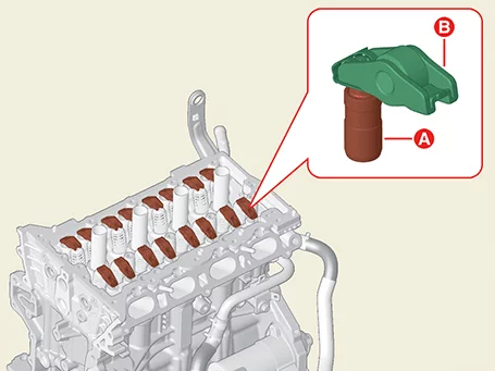
Mount HLA (Hydraulic Valve Gap Adjuster) (A) and swing arm (B) to the cylinder head.
|
| 7. |
Install the cam carrier.
| (1)
|
Remove the hardening sealant, oil, cleaning residue, foreign materials gathered in the bottom of
the cam carrier and on the top of the cylinder head.
|
| (2)
|
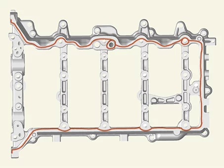
Apply a continuous bead of liquid gasket to the bottom surface of the cam carrier, as shown in
the illustration.
Bead width : 2.5 - 3.5 mm (0.10 - 0.14 in.)
Sealant : Threebond 1217H or equivalent
|
|
•
|
After assembling, check whether the sealant flows into the hole.
|
|
•
|
Cleanly remove the sealant and foreign substances remaining on the cylinder head
and cam carrier.
|
|
|
| (3)
|
The dowel pins on the cam carrier and holes on the top of the cylinder head should be used as a
reference in order to assemble the cam carrier in exact position.
|
| (4)
|
Tighten the cam carrier mounting bolts (A).
Tightening torque :
18.6 - 22.6 N·m (1.9 - 2.3 kgf·m, 13.7 - 16.6 lb·ft)
|
|
•
|
Install the cam carrier within 5 minutes after applying the sealant.
|
|
•
|
Install the camshaft bearing cap within 5 minutes of assembling the cam carrier.
|
|
•
|
The engine running or pressure test should not be performed within 30 minutes
after assembling the cam carrier.
|
|
|
|
| 8. |
Assemble the other parts in the reverse order of disassembly.
|
Install the Cylinder Head to the specified torque.
|
|
Cylinder Head Inspection
Cylinder Head
| 1. |
The flatness of the contact surface between the cylinder block and the manifold is measured using a
precision square and gap gauge.
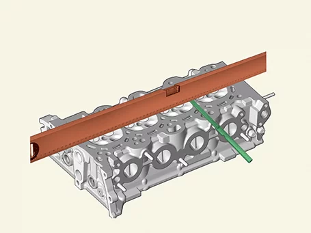
Flatness of cylinder head gasket surfac
Less than 0.05 mm (0.0020 in.) for total area
Less than 0.02 mm (0.0008 in.) for a section of 100 mm (3.9370 in.) X 100 mm (3.9370 in.)
|
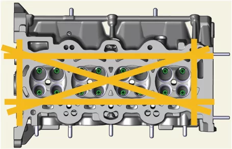
Less than 0.100 mm (0.0039 in.)
|
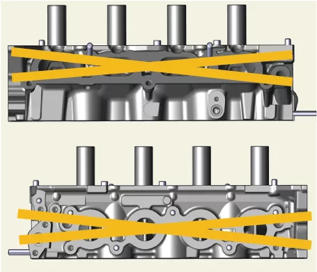
|
| 2. |
Inspect for cracks.
Check the combustion chamber, intake ports, exhaust ports and cylinder block surface for cracks. If
cracked, replace the cylinder head.
|
Valve and Valve Spring
| 1. |
Inspect the valve stem and valve guides.
| (1)
|
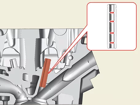
Using a caliper gauge, measure the inner diameter of the valve guide.
Guide inner diameter (intake/exhaust) :
5.500 - 5.512 mm (0.2165 - 0.2170 in.)
|
|
| (2)
|
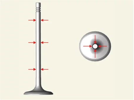
Measure the external diameter of the valve stem by using the micro meter.
Valve stem external diameter
Intake : 5.465 - 5.480 mm (0.2152 - 0.2157 in.)
Exhaust : 5.458 - 5.470 mm (0.2149 - 0.2153 in.)
|
|
| (3)
|
Calculate the clearance between the valve guide and valve stem using measured value.
If the clearance is greater than specification, replace the valve or the cylinder head.
Valve stem-to-guide clearance :
Intake : 0.020 - 0.047 mm (0.0008 - 0.0018 in.)
Exhaust : 0.030 - 0.054 mm (0.0012 - 0.0021 in.)
|
|
|
| 2. |
Inspect the valve.
| (1)
|
Check the wear of the valve contact surface and replace the valve if wear is excessive.
|
| (2)
|
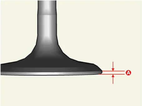
Check the valve head margin thickness (A).
Replace the valve in case the margin is less than the specified value.
Valve head thickness (Margin)
Specifications
Intake : 1.47 - 1.71 (0.0555 - 0.0673 in.)
Exhaust : 1.55 - 1.71 (0.0610 - 0.0728 in.)
|
|
| (3)
|
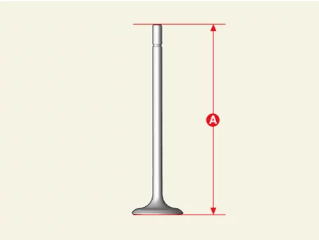
Check the valve length (A).
Valve length
[Standard]
Intake : 102.22 mm (4.0244 in.)
Exhaust : 104.04 mm (4.0961 in.)
Intake : 101.97 mm (4.0146 in.)
Exhaust : 103.79 mm (4.0862 in.)
|
|
| (4)
|
Check valve stem tip for wear and replace the valve if wear is excessive.
|
|
| 3. |
Inspect the valve seat and guide.
| (1)
|
Check the valve seat for evidence of overheating and valve face contact condition. Replace the
cylinder head if the valve seat is worn.
|
| (2)
|
Check the valve guide for wear. If the valve guide is worn, replace the cylinder head.
|
|
| 4. |
Inspect the valve spring.
| (1)
|
Using a steel square ruler, measure the out-of-square of the valve spring.
Squareness (Intake, Exhaust) : 1.5° or less
|
|
| (2)
|
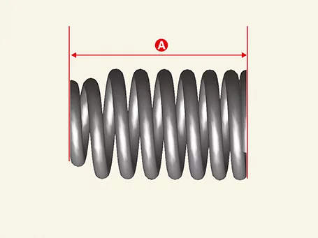
Using a vernier calipers, measure the free length (A) of the valve spring.
Replace the valve spring in case the free length is out of the specified value.
Valve spring
Free length : 45.93 mm (1.8083 in.)
|
|
|
Hydraulic Lash Adjuster (HLA)
* HLA : Hydraulic Lash Adjuster
Hold the lower part of the HLA filled with engine oil (B) and when the cap (A) moves, press the cap (A) by hand
to change the HLA.
Problem
|
Suspected Cause
|
Repair
|
1. Noise occurs for several seconds when starting the engine
|
Normal condition
|
When the engine is stopped, the oil is leaking from the HLA, so the noise disappears when the oil pressure
reaches a steady state
|
2. Continuous noise occurs when starting the engine after leaving it for 48 hours or more.
|
Air ingress due to oil leakage in high pressure chamber in HLA
|
When the engine is operated at 2,000-3,000 rpm, the noise disappears within 15 minutes
If not,
see Table 7
|
Do not run the engine above 3,000 rpm. HLA can be damaged.
|
|
Continuous noise when starting the engine immediately after disassembling and assembling the cylinder head
|
Lack of oil in the cylinder head oil passage
|
Continuous noise when starting after excessive engine cranking
|
Air ingress due to oil leakage in high pressure chamber in HLA, lack of oil in the cylinder head
oil passage
|
5. Continuous noise when starting the engine after replacing HLA
|
6. Continuous noise during idling immediately after high-speed driving
|
Inadequate amount of oil
|
Check the oil level and add or drain oil
|
Excessive air in the oil
|
Check the oil supply system
|
Oil deterioration
|
Change the oil
|
7. Continuous noise over 15 minutes
|
Low oil pressure
|
Check the oil pressure and the oil supply system of each part of the engine.
|
HLA defect
|
after removing the mounting cylinder head cover, check the HLA and replace the spongy HLA
|
* Spongy : Air flows into the high-pressure chamber inside the HLA, and the HLA is pressed even if it is pressed
by hand.
Cylinder Head Disassembly
Tool Name / Number
|
Illustration
|
Description
|
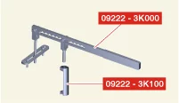
Valve spring compressor
09222 - 3K000
Valve spring compressor adapter
09222 - 3K100
|
|
Removal and installation of intake and exhaust valves
|
|
Identify, valves and valve springs as they are removed so that each item can be reinstalled in its
original position.
|
| 1. |
Remove the valve.
| (1)
|
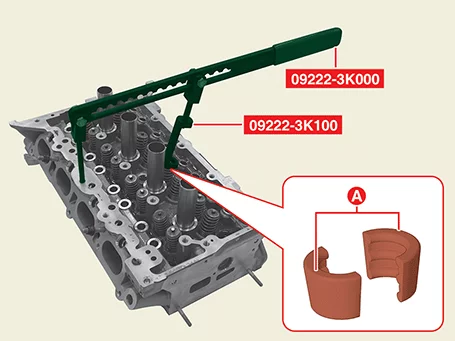
Using the SST (09222 - 3K000, 09222 - 3K100), compress the valve spring and remove the retainer
lock (A).
|
•
|
When installing the SST, insert the front support directly into the bolt hole on
the cylinder head.
|
|
•
|
Do not press valve retainer more than 12 mm (0.47 in.).
|
|
|
| (2)
|
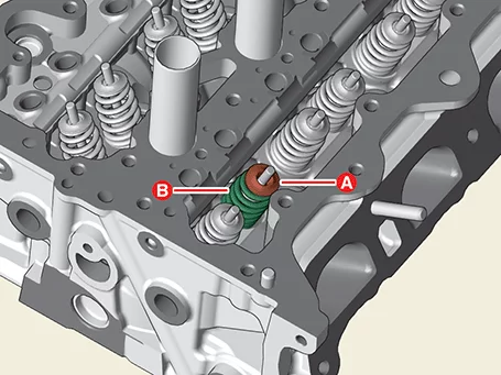
Remove the retainer (A) and the valve spring (B).
|
| (3)
|
Remove the valve (A).
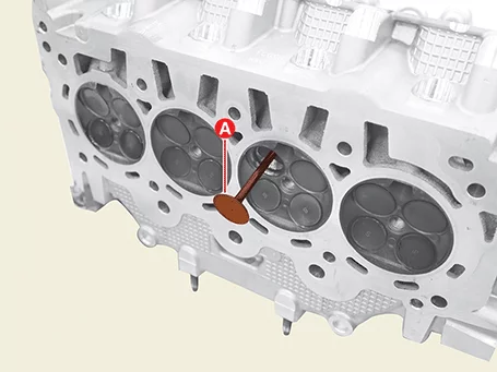
|
| (4)
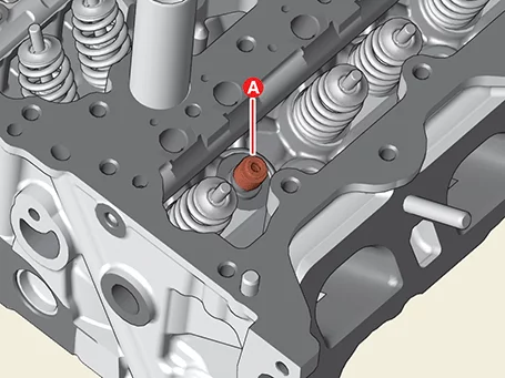
|
Remove the valve stem seal (A).
|
|
Do not reuse valve stem seal.
|
|
Cylinder Head Reassembly
Tool Name / Number
|
Illustration
|
Description
|
Valve spring compressor
09222 - 3K000
Valve spring compressor adapter
09222 - 3K100
|
|
Removal and installation of intake and exhaust valves
|
Valve stem seal installer
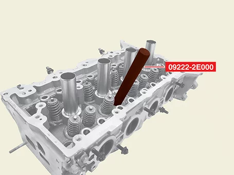
09222 - 2E000
|
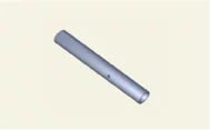
|
Used for installing valve stem seal
|
Steel ball installer
0K221 - 2M100
|
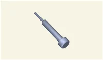
|
Used for installing steel ball
|
|
•
|
Thoroughly clean all parts to be assembled.
|
|
•
|
Before installing the parts, apply fresh engine oil to all sliding and rotating surface.
|
|
•
|
The existing valve stem seal must be replaced with a new one (Do not reuse).
|
|
| 1. |
Install the valve.
| (1)
|
After applying engine oil to the valve stem seal, install the new valve stem seal (A) using a
special tool (09222-2E000).
|
•
|
Do not reuse the valve stem seal.
|
|
•
|
If the seal is installed incorrectly, oil may leak through the valve guide, so be
careful.
|
|
|
| (2)
|
Insert the valve (A) into the valve guide.
|
Be careful not to change the positions of the intake and exhaust valves.
|
|
| (3)
|
Install the valve spring (B) and retainer (A).
|
| (4)
|
Install the valve spring retainer lock (A), by using the SST (09222 - 3K000, 09222 - 3K100).
|
When installing the SST, insert the front support directly into the bolt hole on the
cylinder head.
|
|
Do not press valve retainer more than 12 mm (0.47 in.).
|
|
|
| 2. |
Check if the steel ball (A) is installed in the cylinder head when replacing the cylinder head.
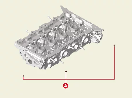
|
| 3. |
If steel ball not installed, be sure to install the steel ball.
| (1)
|
Stick the steel ball (A) to the SST (0K221 - 2M100).
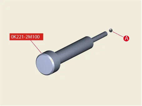
|
| (2)
|
Using a special tool (0K221-2M100) and a hammer, install the steel ball.
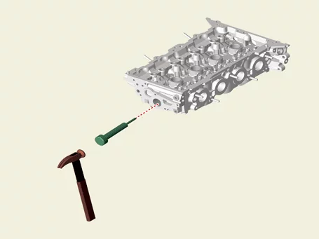
|
|
Other information:
Kia Seltos SP2 (2021-2026) Service Manual: Cruise Control (CC)
Cruise indicator
Set speed
Cruise Control allows the Kia Seltos to maintain a selected speed above 20 mph (30 km/h) without the driver continuously pressing the accelerator pedal. It is most useful on open roads or highways with steady traffic flow.
Kia Seltos SP2 (2021-2026) Service Manual: Vehicle Stability Management (VSM) system
The Vehicle Stability Management (VSM) system in the Kia Seltos provides additional support for vehicle stability and steering response under certain driving conditions.
VSM may assist in the following situations:
When driving on a slippery road surface.
When the system detects a difference in traction between the left and right wheels.



