
Kia Seltos SP2 (2021-2026) Service Manual / Brake System / ESC (Electronic Stability Control) System
Kia Seltos: Brake System / ESC (Electronic Stability Control) System
Contents:
- Components and Components Location
- Description and Operation
- Troubleshooting
- ESC Control Unit Components and Components Location
- ESC Control Unit Removal and Installation
- ESC Control Unit Adjustment
- Front Wheel Speed Sensor Removal and Installation
- Rear Wheel Speed Sensor Removal and Installation
- Rear Wheel Speed Sensor Replacement - 2WD
- ESC OFF Switch Components and Components Location
- ESC OFF Switch Removal and Installation
Components and Components Location
| Component |
[2WD]
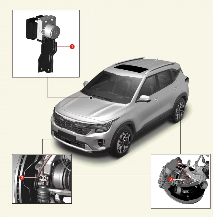
| 1. ESC Control Unit |
2. Front wheel speed sensor 3. Rear wheel speed sensor |
[4WD]
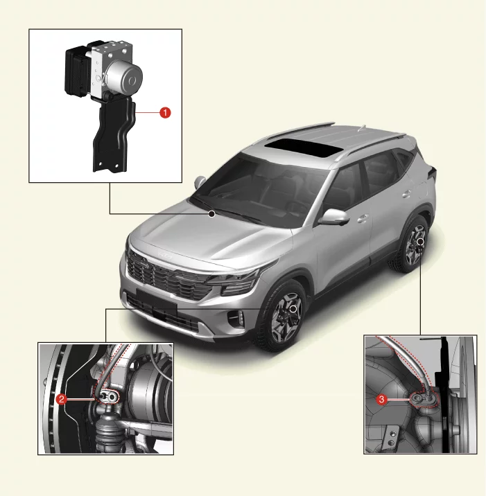
| 1. ESC Control Unit |
2. Front wheel speed sensor 3. Rear wheel speed sensor |
Description and Operation ➤
Troubleshooting ➤
ESC Control Unit Components and Components Location
| Component |
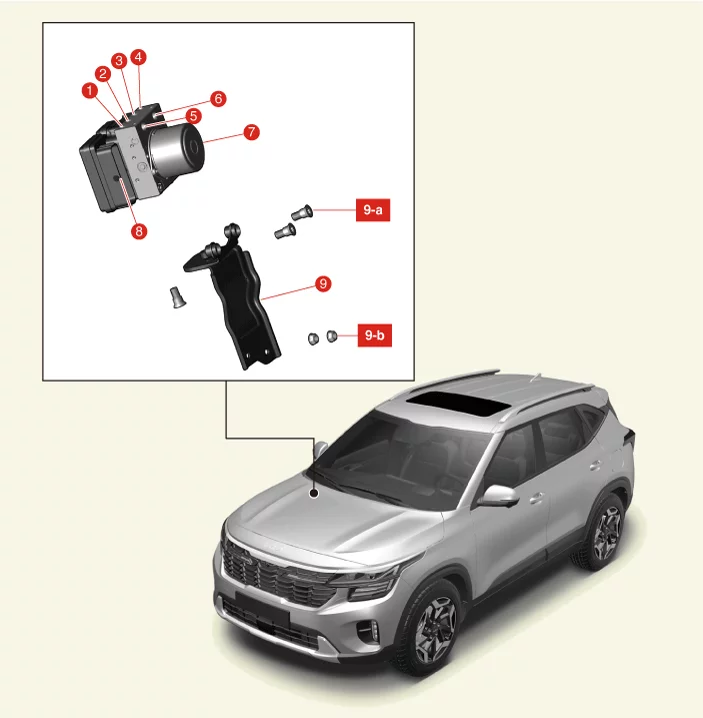
| 1. Front Right (FR) 13.7 - 16.7 N·m (1.4 - 1.7 kgf·m, 10.1 - 12.3 lb·ft) 2. Rear Left (RL) 13.7 - 16.7 N·m (1.4 - 1.7 kgf·m, 10.1 - 12.3 lb·ft) 3. Rear Right (RR) 13.7 - 16.7 N·m (1.4 - 1.7 kgf·m, 10.1 - 12.3 lb·ft) 4. Front Left (FL) 13.7 - 16.7 N·m (1.4 - 1.7 kgf·m, 10.1 - 12.3 lb·ft) 5. Master Cylinder 2 18.6 - 22.6 N·m (1.9 - 2.3 kgf·m, 13.7 - 16.6 lb·ft) |
6. Master Cylinder 1 18.6 - 22.6 N·m (1.9 - 2.3 kgf·m, 13.7 - 16.6 lb·ft) 7. ESC Control Unit (HECU) Motor 8. ESC Control Unit (HECU) Connector 9. ESC Control Unit (HECU) Bracket 9-a. 10.8 - 13.7 N·m (1.1 - 1.4 kgf·m, 8.0 - 10.1 lb·ft) 9-b. 16.7 - 25.5 N·m (1.7 - 2.6 kgf·m, 12.3 - 18.8 lb·ft) |
ESC Control Unit Removal and Installation
| Removal |
When replacing the ESC Control Unit (HECU), extract the variant code from the existing module and input
it to the new HECU using KDS. (Use one of the following lists.)
|

| 1. |
Disconnect the battery negative ( - ) terminal.
|
| 2. |
Remove the engine and transaxle assembly [ "Engine and transaxle
detachment applied only in the case of the 1.6 T-GDI GAMMA II engine."]
(Refer to Engine Mechanical System - "Engine and Transaxle
Assembly")
|
| 3. |
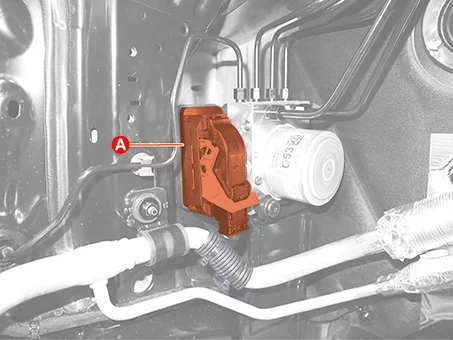
Disconnect the ESC Control Unit (HECU) connector (A).
|
| 4. |
Remove the brake tube flare nut (A), (B), and then disconnect the brake tube.
|
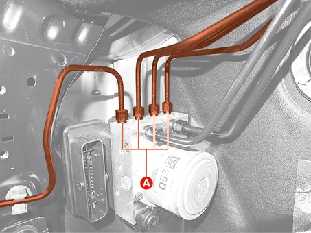
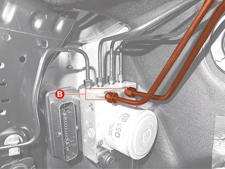
| 5. |
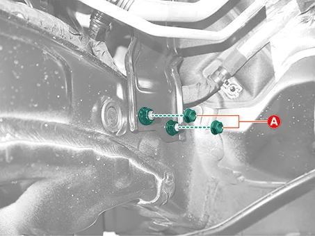
Remove the ESC control unit after removing the nuts (A).
|
| 6. |
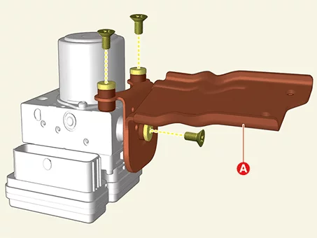
Remove the screws, and then remove the ESC control unit bracket (A).
|
| Installation |
Do not disassemble the ESC Control Unit (HECU). If the HECU is defective, replace it with a new one.
|
| 1. |
Install in reverse order of removal.
|
| 2. |
Fill the brake reservoir with brake fluid and perform air bleeding.
(Refer to Brake System - "Brake Bleeding Procedures")
|
| 3. |
Perform 'ESC Variant Coding', 'Longitudinal G Sensor Calibration', 'Auto Detected Configuration (ESC
Only)' by using KDS.
(Refer to ESC Control Unit - "Adjustment")
|
ESC Control Unit Adjustment
| Diagnostic procedure by using KDS |
Perform below procedures using KDS after or before replacing the ESC Control Unit (HECU).
ESC Variant Coding
Perform this function to optimize Electronic Stability Program (ESP) in accordance with equipped system (ABS/ESP,
HAC, SPAS, etc.) on the vehicle.
(S/W Management → ABS/ESP or Brake → ESC Variant Coding or Auto Variant Coding)
Refer to the KDS screen for operating conditions and details.
|

Longitudinal G Sensor Calibration
Perform this function to reset sensor value of longitudinal G sensor.
(S/W Management → ABS/ESP or Brake → Longitudinal G Sensor Calibration)
Refer to the KDS screen for operating conditions and details.
|
Auto Detected Configuration (ESC Only)
Perform this function to reset configuration such as engine and transmission type, EPB, 4WD and others that set
to HECU during vehicle assembly and allow PCM/ECM to re-configure.
(S/W Management → ABS/ESP or Brake - Auto Detected Configuration (ESC Only))
Refer to the KDS screen for operating conditions and details.
|
Assembly Check
Perform this function to set appropriate gap between brake pad and caliper when Electronic Parking Brake (EPB)
ECU or EPB Caliper is replaced.
(S/W Management → ABS/ESP or Brake → Assembly Check)
Refer to the KDS screen for operating conditions and details.
|
Front Wheel Speed Sensor Removal and Installation
| Removal |
| 1. |
Disconnect the battery negative (-) terminal.
|
| 2. |
Remove the front wheel and tires.
(Refer to Suspension System - "Wheel")
|
| 3. |
Remove the front wheel guard.
(Refer to Body - "Front Wheel Guard")
|
| 4. |
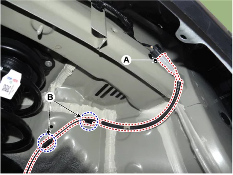
Disconnect the sensor connector (A) and remove the wiring fasteners (B).
|
| 5. |
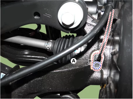
Remove the wheel speed sensor (A) after removing the bolt.
|
| 6. |
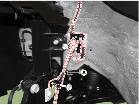
Remove the wheel speed sensor (A) after removing the bolts.
|
| Installation |
| 1. |
Install in reverse order of removal.
|
Rear Wheel Speed Sensor Removal and Installation
| Removal |
Rear Wheel Seed Sensor Wiring [2WD]
| 1. |
Disconnect the battery negative (-) terminal.
|
| 2. |
Remove the luggage side trim.
(Refer to Body - "Luggage Side Trim")
|
| 3. |
Disconnect the rear wheel speed sensor wiring connector (A).
|
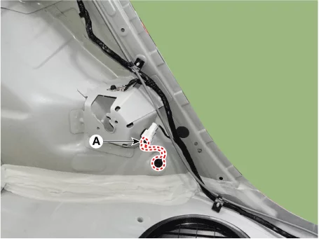
| 4. |
Remove the rear wheel and tires.
(Refer to Suspension System - "Wheel")
|
| 5. |
Remove the rear wheel guard.
(Refer to Body - "Rear Wheel Guard")
|
| 6. |
Disconnect the rear wheel speed sensor connector (A).
|
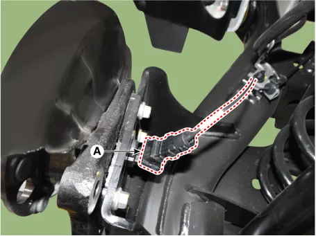
| 7. |
Remove the mounting nut (A).
|
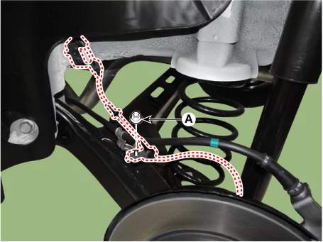
| 8. |
Remove the wheel speed sensor wiring (C) after removing the bolt (A) and fastener (B).
|
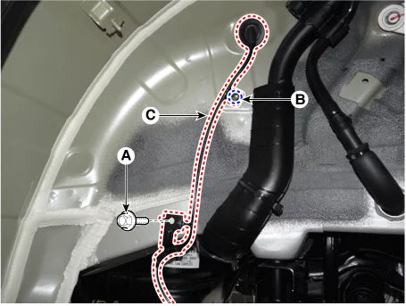
Rear Wheel Speed Sensor [2WD]
| 1. |
Disconnect the battery negative (-) terminal.
|
| 2. |
Remove the rear wheel and tires.
(Refer to Suspension System - "Wheel")
|
| 3. |
Remove the rear brake disc.
(Refer to Brake System - "Rear Brake Disc")
|
| 4. |
Disconnect the rear wheel speed sensor connector (A).
|
| 5. |
Remove the rear hub bearing and dust cover assembly (A) after removing the bolts.
|
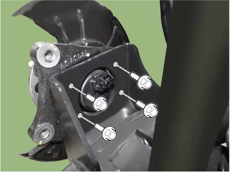
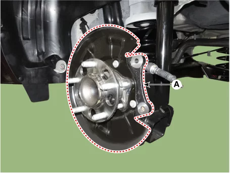
Rear Wheel Speed Sensor [4WD]
| 1. |
Disconnect the battery negative (-) terminal.
|
| 2. |
Remove the luggage side trim.
(Refer to Body - "Luggage Side Trim")
|
| 3. |
Disconnect the rear wheel speed sensor wiring connector (A).
|
| 4. |
Remove the rear wheel and tires.
(Refer to Suspension System - "Wheel")
|
| 5. |
Remove the rear wheel guard.
(Refer to Body - "Rear Wheel Guard")
|
| 6. |
Remove the rear wheel speed sensor (A) after removing the bolt.
|
| 7. |
Disconnect the EPB actuator connector (A).[EPB]
|
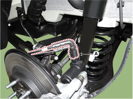
| 8. |
Separate the wiring bracket after removing the nut (A).
|
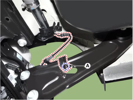
| 9. |
Remove the wheel speed sensor wiring (C) after removing the bolt (A) and fastener (B).
|
| Installation |
| 1. |
Install in reverse order of removal.
|
Rear Wheel Speed Sensor Replacement - 2WD
| Special Service Tool |
|
Tool Name / Number |
Illustration |
Description |
|
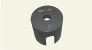
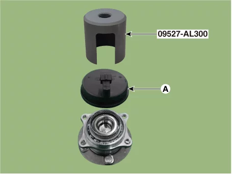
Sensor cap installer 09527 - AL300 |
|
Used for installing wheel speed sensor cap (for outer diameter : 67.2 mm, 2.64 in.) |
| Replacement |
Rear Wheel Speed Sensor Cap
| 1. |
Remove the rear wheel hub bearing assembly.
(Refer to Driveshaft and Axle - "Rear Hub Assembly)
|
| 2. |
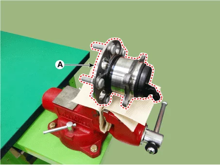
Fix the rear hub bearing assembly (A) with a vise.
|
| 3. |
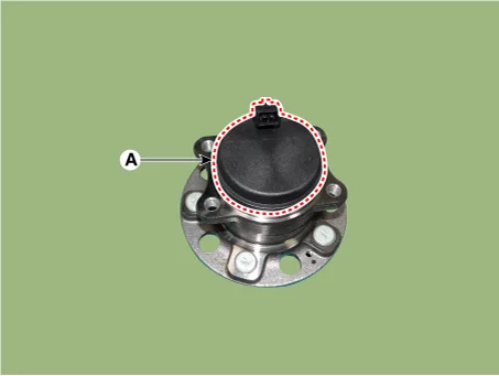
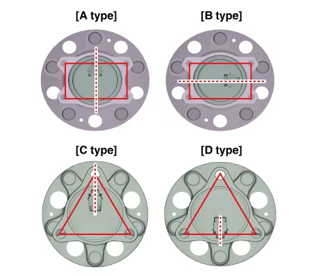
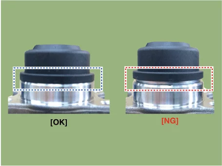
Check the installation position of the sensor cap (A).
|
| 4. |
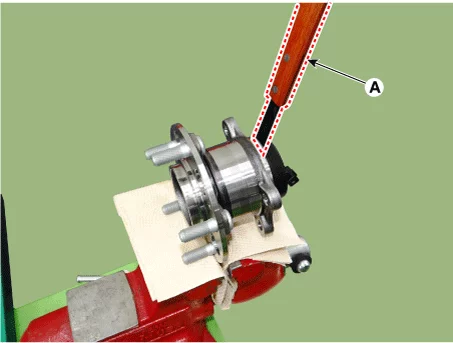
Remove the sensor cap by hammering on a gap between the sensor cap and hub bearing assembly using a
scraper (A).
|
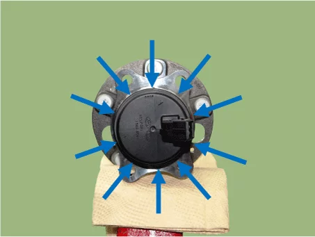
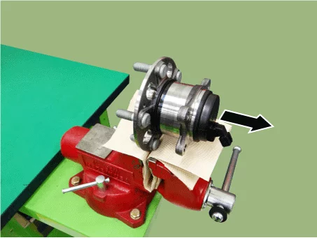
| 5. |
Check for distortion of damage of the tone wheel or encoder (A).
|
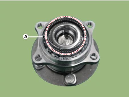
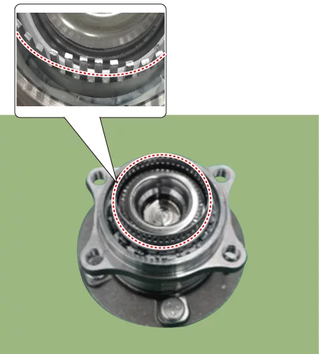
| 6. |
Position the sensor cap to the same direction of sensor cap connector (A) as you checked before removing.
|
| 7. |
Install the sensor cap (A) with the special service tool (09527 - AL300).
|
| 8. |
Install the rear wheel hub bearing assembly.
(Refer to Driveshaft and Axle - "Rear Hub Assembly)
|
ESC OFF Switch Components and Components Location
| Component |
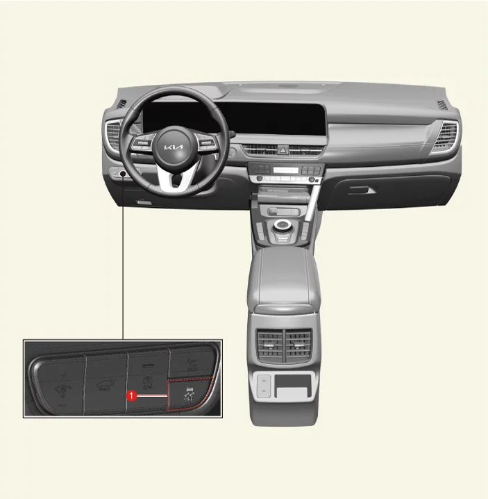
| 1. ESC OFF switch |
ESC OFF Switch Removal and Installation
| Removal |
| 1. |
If the ESC OFF switch needs to be replaced, replace the headlamp leveling switch.
(Refer to Body Electrical System - "Head Lamp Leveling Switch)
|
| Installation |
| 1. |
Install in reverse order of removal.
|


Other information:
Kia Seltos SP2 (2021-2026) Service Manual: Cruise Control (CC)
Cruise indicator Set speed Cruise Control allows the Kia Seltos to maintain a selected speed above 20 mph (30 km/h) without the driver continuously pressing the accelerator pedal. It is most useful on open roads or highways with steady traffic flow.The battery supplies electrical power for starting the engine and supports many electrical devices installed in the Kia Seltos. Keeping the battery in good condition helps ensure reliable starting and stable electrical system operation. For best battery service Keep the battery securely mounted. Keep the top of the battery clean and dry.