
Kia Seltos: Suspension System / Front Suspension System
Contents:
- Components and Components Location
- Front Strut Assembly Components and Components Location
- Front Strut Assembly Removal and Installation
- Front Strut Assembly Disassembly
- Front Strut Assembly Inspection
- Front Strut Assembly Reassembly
- Front Lower Arm Components and Components Location
- Front Lower Arm Removal and Installation
- Front Lower Arm Inspection
- Front Lower Arm Replacement
- Front Lower Arm Replacement - Lower Arm 'G' Bushing
- Front Stabilizer Bar Components and Components Location
- Front Stabilizer Bar Removal and Installation
- Front Stabilizer Bar Inspection
- Front Sub Frame Removal and Installation
Components and Components Location
| Component |
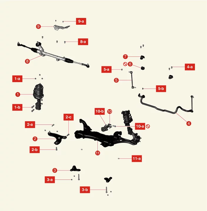
| 1. Front Strut Assembly 1-a. 53.9 - 73.5 N·m (5.5 - 7.5 kgf·m, 39.8 - 54.2 lb·ft) 1-b. 137.3 - 156.9 N·m (14.0 - 16.0 kgf·m, 101.3 - 115.7 lb·ft) 2. Front Lower Arm 2-a. 58.8 - 70.6 N·m (6.0 - 7.2 kgf·m, 43.4 - 52.1 lb·ft) 2-b. 117.7 - 137.3 N·m (12.0 - 14.0 kgf·m, 86.8 - 101.3 lb·ft) 2-c. 156.9 - 176.5 N·m (16.0 - 18.0 kgf·m, 115.7 - 130.2 lb·ft) 3. Front Sub Frame Stay 3-a. 44.1 - 58.8 N·m (4.5 - 6.0 kgf·m, 32.5 - 43.4 lb·ft) 3-b. 176.5 - 196.1 N·m (18.0 - 20.0 kgf·m, 130.2 - 144.7 lb·ft) 4. Front Stabilizer Bar 4-a. 49.0 - 63.7 N·m (5.0 - 6.5 kgf·m , 36.2 - 47.0 lb·ft) 5. Front Stabilizer Bar Link 5-a. 98.1 - 117.7 N·m (10.0 - 12.0 kgf·m, 72.3 - 86.8 lb·ft) 5-b. 98.1 - 117.7 N·m (10.0 - 12.0 kgf·m, 72.3 - 86.8 lb·ft) |
6. Front Stabilizer Bar Bushing 7. Front Stabilizer Bar Bracket 8. Steering Gear Box 8-a. 88.3 - 107.9 N·m (9.0 - 11.0 kgf·m, 65.1 - 79.6 lb·ft) 9. Steering Gear Box Heat Protector 9-a. 7.8 - 11.8 N·m (0.8 - 1.2 kgf·m, 5.8 - 8.7 lb·ft) 10. Roll Rod Bracket 10-a. 107.9 - 127.5 N·m (11.0 - 13.0 kgf·m, 79.6 - 94 lb·ft) 10-b. 49.0 - 63.7 N·m (5.0 - 6.5 kgf·m, 36.2 - 47 lb·ft) 11. Front Sub Frame 11-a. 176.5 - 196.1 N·m (18.0 - 20.0 kgf·m, 130.2 - 144.7 lb·ft) |
Front Strut Assembly Components and Components Location
| Component |
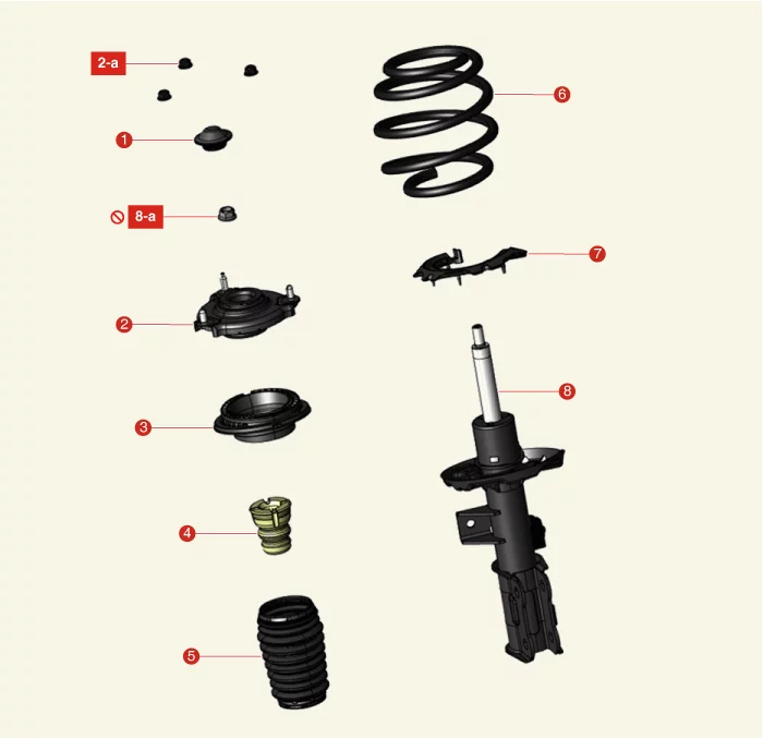
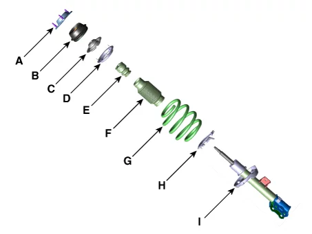
| 1. Insulator Cap 2. Insulator Assembly 2-a. 53.9 - 73.5 N·m (5.5 - 7.5 kgf·m, 39.8 - 54.2 lb·ft) 3. Strut Bearing 4. Bumper Stopper |
5. Dust Cover 6. Coil Spring 7. Spring Lower Pad 8. Strut Assembly 8-a. 98.1 - 107.9 N·m (10.0 - 11.0 kgf·m, 72.3 - 79.6 lb·ft) |
Front Strut Assembly Removal and Installation
| Removal |
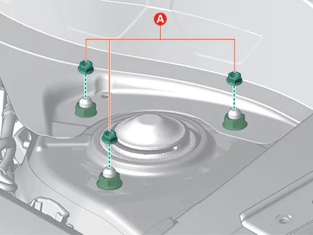
| 1. |
Remove the front strut upper nuts (A).
|
| 2. |
Remove the front wheel and tires.
(Refer to Tires/Wheels - "Wheel")
|
| 3. |
Remove the bolt, and then separate the brake hose bracket (A).
|
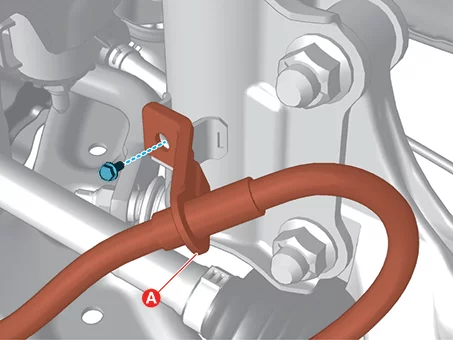
| 4. |
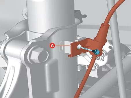
Separate the front wheel speed sensor wire bracket (A) after removing the bolt.
|
| 5. |
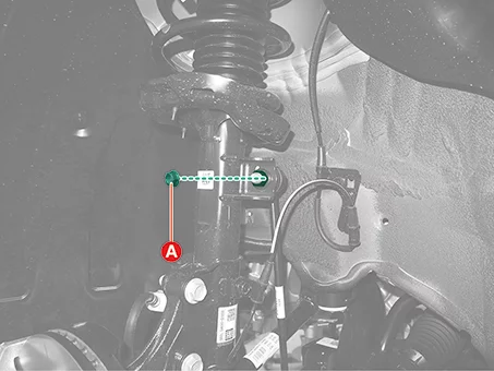
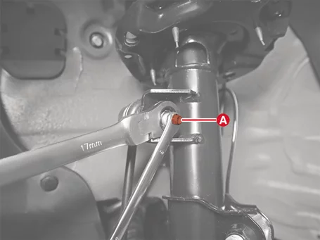
Remove the stabilizer bar link (A) from the front strut assembly after removing the nut.
|

| 6. |
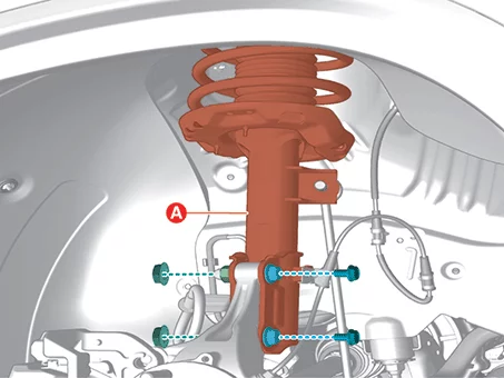
Remove the front strut assembly (A) from the front axle after removing the bolts and nuts.
|
| Installation |
| 1. |
Install in reverse order of removal.
|
Front Strut Assembly Disassembly
| Special Service Tool |
|
Tool Name / Number |
Illustration |
Description |
|
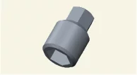
Shock absorber lock nut remover. 09546 - 3X100 |
|
Used for removal or installing of front strut lock nut. |
| Disassembly |
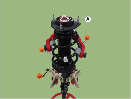
| 1. |
Remove the insulator cap (A).
|
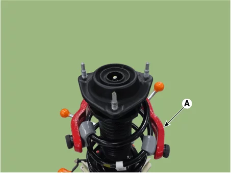
| 2. |
Compress the coil spring slightly until it is tensioned using the spring compressor (A).
|

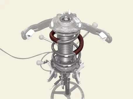

| 3. |
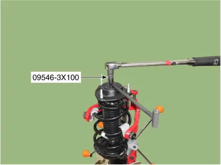
Remove the self locking nut using SST (09546 - 3X100).
|
| 4. |
Disassemble the front strut assembly.
|
Front Strut Assembly Inspection
| Inspection |
| 1. |
Check the strut insulator bearing for wear and damage.
|
| 2. |
Check the rubber parts for damage and deterioration.
|
| 3. |
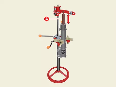
Compress and extend the piston rod (A) and check that there is no abnormal resistance or unusual sound
during operation.
|
| Disposal |
| 1. |
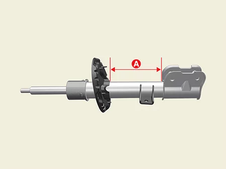
Fully extend the strut rod.
|
| 2. |
Drill a hole on the A section to remove gas from the cylinder.
|
Front Strut Assembly Reassembly
| Special Service Tool |
|
Tool Name / Number |
Illustration |
Description |
|
Shock absorber lock nut remover. 09546 - 3X100 |
|
Used for removal or installing of front strut lock nut. |
| Reassembly |
| 1. |
Reassemble the front strut assembly.
|
| 2. |
Compress the coil spring slightly until it is tensioned using the spring compressor (A).
|
| 3. |
Install the self locking nut using SST (09546 - 3X100).
|
| 4. |
Install the insulator cap (A).
|
Front Lower Arm Components and Components Location
| Component |
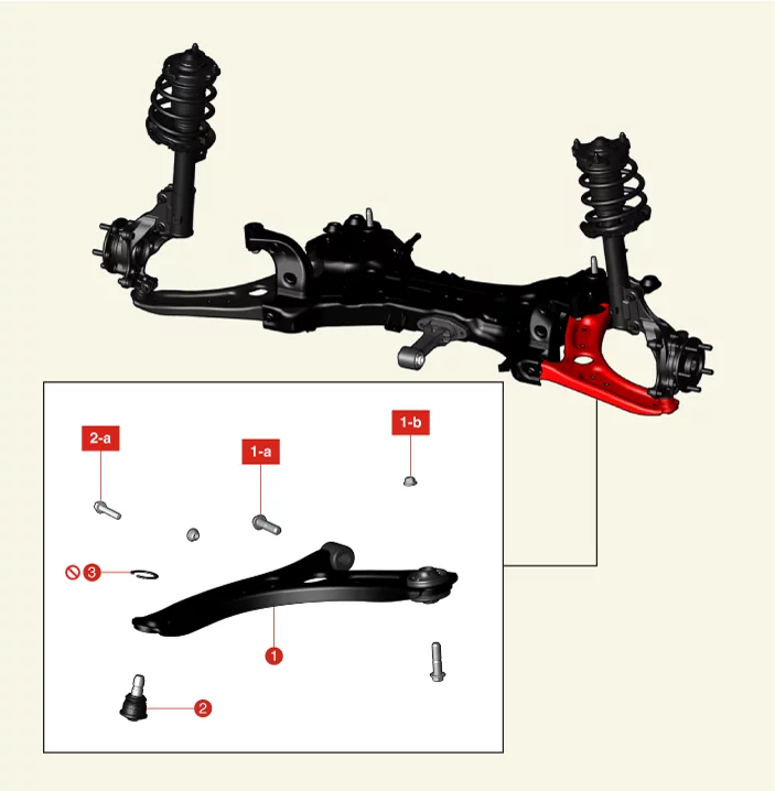
| 1. Front Lower Arm Assembly 1-a. 156.9 - 176.5 N·m (16.0 - 18.0 kgf·m, 115.7 - 130.2 lb·ft) 1-b. 117.7 - 137.3 N·m (12.0 - 14.0 kgf·m, 86.8 - 101.3 lb·ft) |
2. Front Lower Arm Ball Joint 2-a. 58.8 - 70.6 N·m (6.0 - 7.2 kgf·m, 43.4 - 52.1 lb·ft) 3. Snap Ring |
Front Lower Arm Removal and Installation
| Special Service Tool |
|
Tool Name / Number |
Illustration |
Description |
|
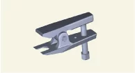
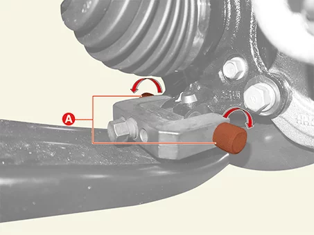
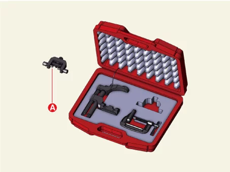
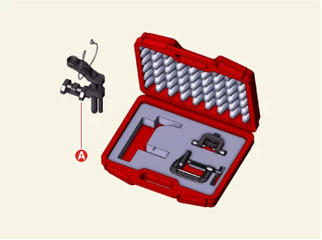
Ball joint puller 0K545 - A9100 |
|
Used for removal of front lower arm ball joint |
| Removal |
| 1. |
Remove the front wheel and tires.
(Refer to Tires/Wheels - "Wheel")
|
| 2. |
Remove the engine room under cover.
G 1.6 T-GDI GAMMA II (Refer to Engine Mechanical System - "Engine Room
Under Cover")
G 2.0 MPI NU (Refer to Engine Mechanical System - "Engine Room Under
Cover")
|
| 3. |
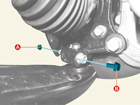
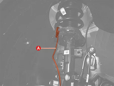
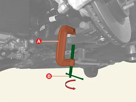
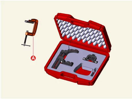
Separate the lower arm ball joint from the front axle.
|
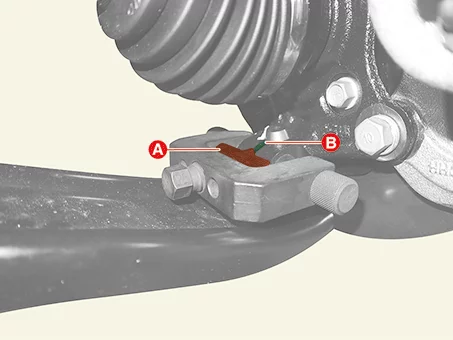
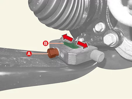
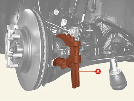
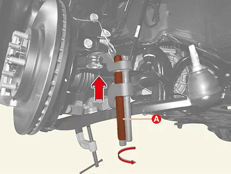
| 4. |
Remove the front lower arm (A) after removing the bolt and nut.
|
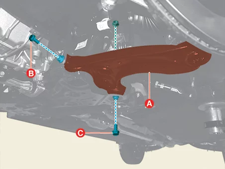
| Installation |
| 1. |
Install in reverse order of removal.
|
| 2. |
Check the alignment.
(Refer to Alignment - "Repair Procedures")
|
Front Lower Arm Inspection
| Inspection |
| 1. |
Check the bushing for wear or aging.
|
| 2. |
Check the lower arm for bent or damaged.
|
| 3. |
Check all bolts.
|
| 4. |
Check the ball joint rotation torque.
If there is an abnormality, replace the ball joint.
|
| 5. |
Check the ball stud (A) axial free play, In case of any free play exist, replace the ball joint (B).
|
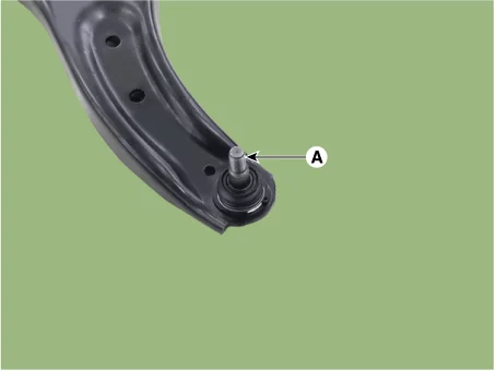
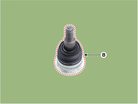
Front Lower Arm Replacement
| Replacement |
| 1. |
Remove the front lower arm.
(Refer to Front Suspension System - "Front Lower Arm")
|
| 2. |
Remove the snap ring (A).
|
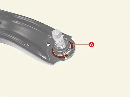
| 3. |
Remove the front lower arm ball joint.
|
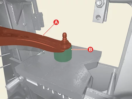
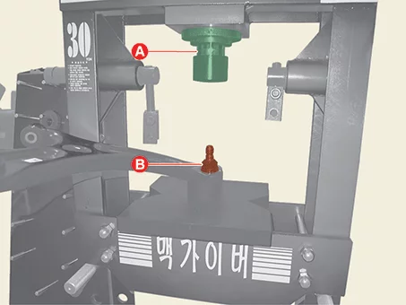
| 4. |
Install the front lower arm ball joint.
|
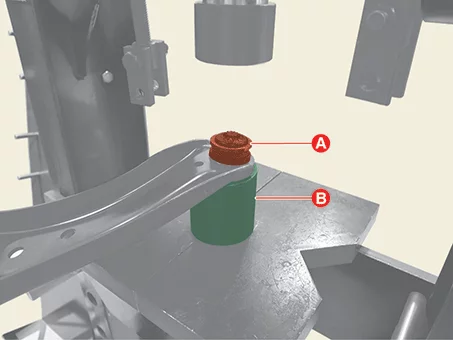
| 5. |
Install the snap ring (A).
|
Front Lower Arm Replacement - Lower Arm 'G' Bushing
| Special Service Tool |
|
Tool Name / Number |
Illustration |
Description |
|
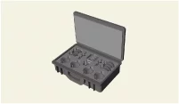
Lower arm 'G' bushing replacement tool 09545 - AL100 |
|
Used for replacement of the lower arm 'G' bushing |
| Replacement - Lower Arm 'G' Bushing |
Replace the lower arm 'G' bushing if it only has a crack, noise from bushing without cracks can be
improved by applying silicone oil.
|
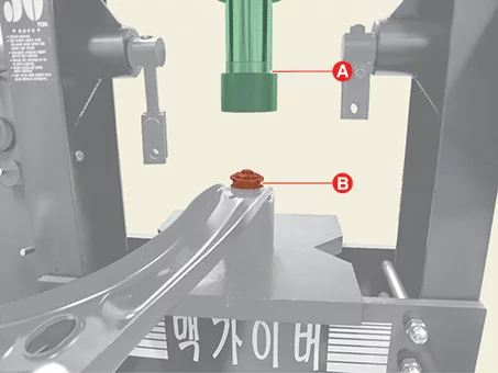
| 1. |
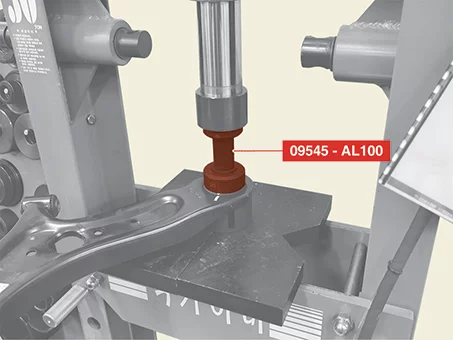
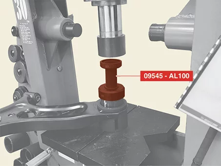
Replace the lower arm 'G' bushing by using the SST (09545 - AL100).
|
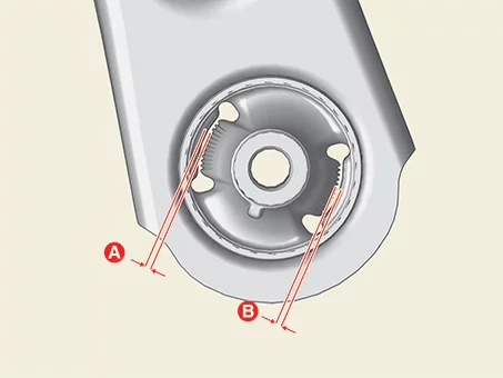
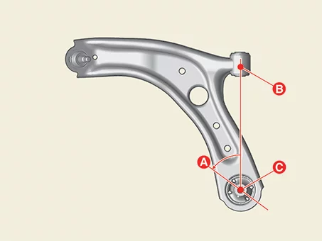
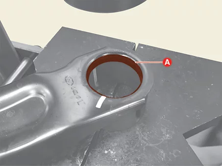
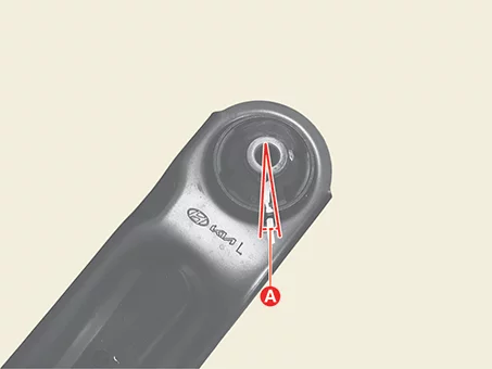
Front Stabilizer Bar Components and Components Location
| Component |
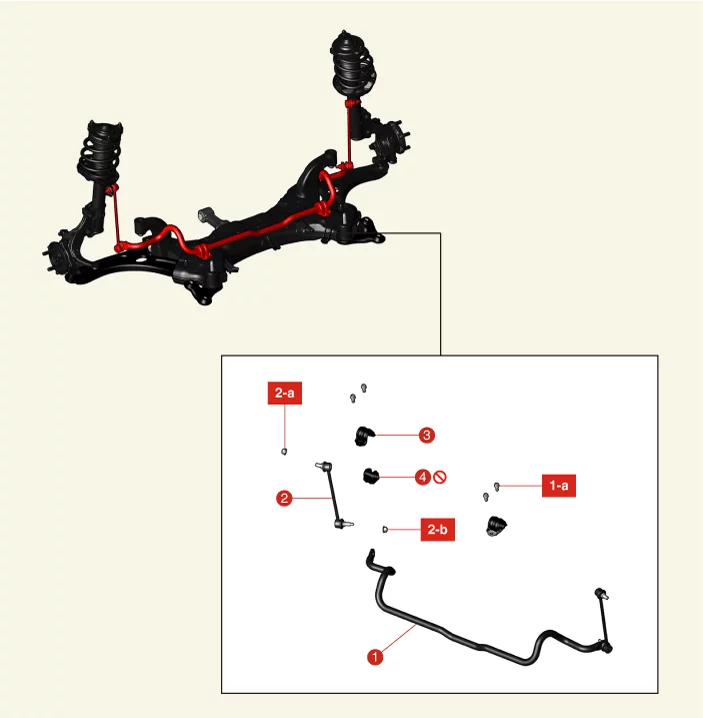
| 1. Front Stabilizer Bar 1-a. 49.0 - 63.7 N·m (5.0 - 6.5 kgf·m, 36.2 - 47 lb·ft) 2. Front Stabilizer Bar Link 2-a. 98.1 - 117.7 N·m (10.0 - 12.0 kgf·m, 72.3 - 86.8 lb·ft) 2-b. 98.1 - 117.7 N·m (10.0 - 12.0 kgf·m, 72.3 - 86.8 lb·ft) |
3. Front Stabilizer Bar Bracekt 4. Front Stabilizer Bar Bushing |
Front Stabilizer Bar Removal and Installation
| Removal |
| 1. |
Remove the front wheel and tires.
(Refer to Tires/Wheels - "Wheel")
|
| 2. |
Separate the front stabilizer bar link after removing the nut (A).
|
| 3. |
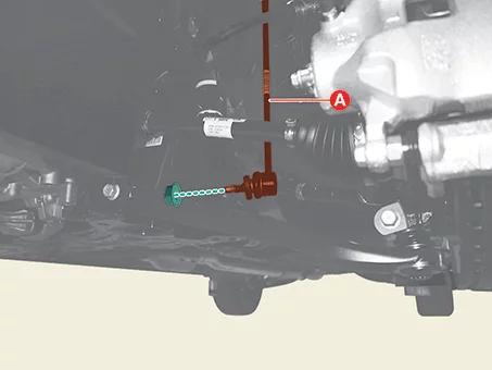
Remove the front stabilizer bar link (A) after removing the nut.
|
| 1. |
Remove the front sub-frame.
(Refer to Suspension System - "Front Sub Frame")
|
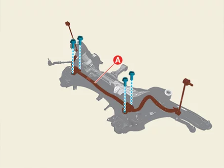
| 2. |
Remove the front stabilizer bar (A) after removing the bolts.
|
| 3. |
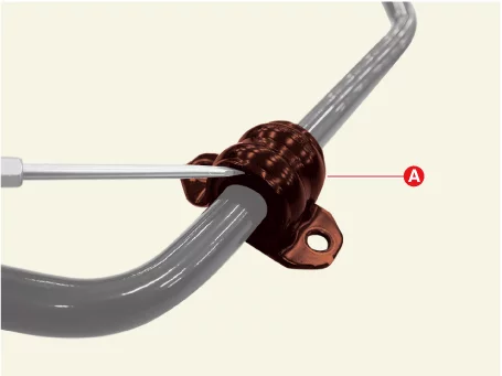
Remove the front stabilizer bar bracket (A) using a flat-head screwdriver.
|
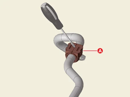
| 4. |
Remove the front stabilizer bar bushing (A) using a flat-head screw driver.
|
| Installation |
| 1. |
Install in reverse order of removal.
|
Front Stabilizer Bar Inspection
| Inspection |
| 1. |
Check the stabilizer bar bushing for damage.
|
| 2. |
Check the stabilizer bar link ball joint for damage.
|
Front Sub Frame Removal and Installation ➤


Other information:
Kia Seltos SP2 (2021-2026) Service Manual: ESC system
The Electronic Stability Control (ESC) system in the Kia Seltos is designed to help stabilize the vehicle during cornering and other driving maneuvers where traction may be reduced. ESC applies braking force to individual wheels and works with the vehicle management system to help maintain stability when the Kia Seltos begins to lose traction or directional control.Kia Seltos SP2 (2021-2026) Service Manual: Lane Keeping Assist (LKA)
Lane Keeping Assist (LKA) in the Kia Seltos is designed to help detect lane markings or road edges while driving above a certain speed. If the vehicle begins to leave its lane without the turn signal being used, LKA may warn the driver and may assist steering to help keep the vehicle within the lane.