
Kia Seltos: Engine Control / Fuel System / Fuel Delivery System
Contents:
- Fuel Pressure Test
- Release Residual Pressure in Fuel Line
- Delivery Pipe Components and Components Location
- Delivery Pipe Removal and Installation
- Filler-Neck Assembly Components and Components Location
- Filler-Neck Assembly Removal and Installation
- Fuel Filter Components and Components Location
- Fuel Filter Removal and Installation
- Fuel Line Components and Components Location
- Fuel Line Removal and Installation
- Fuel Pressure Regulator Components and Components Location
- Fuel Pressure Regulator Removal and Installation
- Fuel Pump Components and Components Location
- Fuel Pump Removal and Installation
- Fuel Pump Module Specification
- Fuel Pump Module Components and Components Location
- Fuel Pump Module On Vehicle Inspection
- Fuel Pump Module Removal and Installation
- Fuel Sender Specification
- Fuel Sender Components and Components Location
- Fuel Sender On Vehicle Inspection
- Fuel Sender Removal and Installation
- Fuel Tank Specification
- Fuel Tank Components and Components Location
- Fuel Tank Removal and Installation
- Injector Specification
- Injector Components and Components Location
- Injector Description and Operation
- Injector On Vehicle Inspection
- Injector Removal and Installation
Fuel Pressure Test
| Special Service Tool |
|
Tool Name / Number |
Illustration |
Description |
|
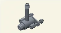
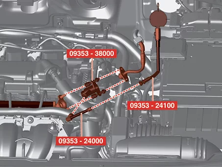
Fuel pressure gauge adapter 09353 - 38000 |
|
Used for connecting between the delivery pipe and the fuel feed line |
|
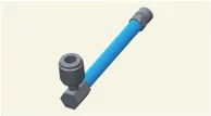
Fuel pressure gauge adapter 09353 - 24000 |
|
Used for connecting between the fuel pressure gauge adapter and the fuel pressure gauge |
|
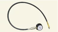
Fuel pressure gauge 09353 - 24100 |
|
Used for measuring the pressure in fuel line |
| Fuel Pressure Test |
| 1. |
Release the residual pressure in fuel line.
(Refer to Fuel Delivery System - "Release Residual Pressure in Fuel
Line")
|

| 2. |
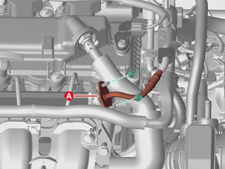
Install the Special Service Tool (SST).
|
| 3. |
Check the leakage in the fuel line and SST installation area with IG ON.
|
| 4. |
Fuel pressure inspection
|
| 5. |
Release the residual pressure in fuel line.
(Refer to Fuel Delivery System - "Release Residual Pressure in Fuel
Line")
|
| 6. |
Test End
|
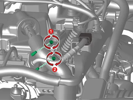
Release Residual Pressure in Fuel Line
| Release Residual Pressure in Fuel Line |
|
| 1. |
Disconnect the battery negative ( - ) terminal.
|
| 2. |
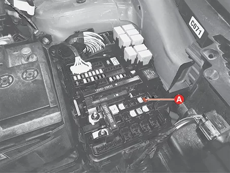
Remove the fuel pump fuse (A) after opening the engine room junction block cover.
|
| 3. |
Connect the battery negative ( - ) terminal.
|
| 4. |
Start the vehicle (idling state) and when the engine stops by itself due to all of the fuel in the fuel
line is exhausted, turn the IG OFF.
|
| 5. |
Proceed with the service or repair.
|
| 6. |
Reinstall / reconnect all components in reverse order of removal. Start engine and confirm proper
operation, and make sure there are no fuel leaks.
|
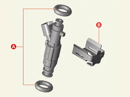
Delivery Pipe Components and Components Location
| Component Location |
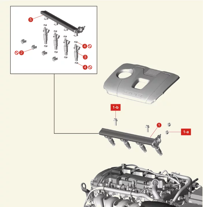
| 1. Delivery Pipe & Injector 1-a. 8.8 - 11.8 N·m (0.9 - 1.2 kgf·m, 6.5 - 8.7 lb·ft) 1-b. 18.6 - 23.5 N·m (1.9 - 2.4 kgf·m, 13.7 - 17.4 lb·ft) |
2. Clip 3. Injector 4. O-ring 5. Delivery Pipe |
Delivery Pipe Removal and Installation
| Removal |
Since there is a risk of injury due to high pressure fuel leakage, do not perform any work right after
the engine is stopped.
|

Cover the connection with a clean cloth since the residual fuel may be released after "Release Residual
Pressure in Fuel Line" procedures.
|
| 1. |
Release the residual pressure in fuel line.
(Refer to Fuel Delivery System - "Release Residual Pressure in Fuel
Line")
|
| 2. |
Disconnect the battery negative ( - ) terminal.
|
| 3. |
Remove the engine cover.
(Refer to Engine Mechanical System - "Engine Cover")
|
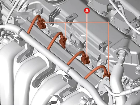
| 4. |
Disconnect the injector connectors (A).
|
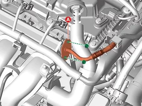
| 5. |
Remove the fuel feed tube (A) after removing the nuts.
|
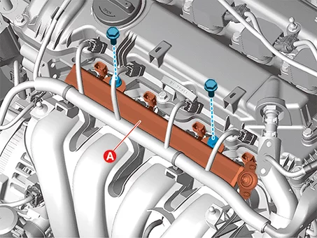
| 6. |
Remove the delivery pipe (A) after removing the bolts.
|
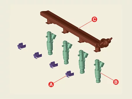
| 7. |
Remove the injector (B) from the delivery pipe (C) after removing the clip (A).
|
| Installation |
| 1. |
Install in reverse order of removal.
|
Filler-Neck Assembly Components and Components Location
| Component Location |
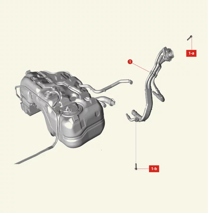
| 1. Filler-neck Assembly 1-a. 3.9 - 5.9 N·m (0.4 - 0.6 kgf·m, 2.9 - 4.3 lb·ft, 34.7 - 52.1 lb·in) 1-b. 8.8 - 9.8 N·m (0.9 - 1.0 kgf·m, 6.5 - 7.2 lb·ft) |
Filler-Neck Assembly Removal and Installation
| Removal |
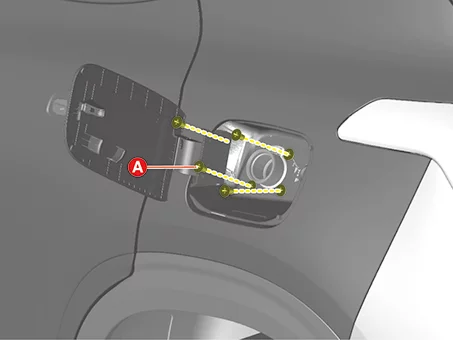
| 1. |
Remove the filler-neck screws (A) after opening the fuel filler door.
|
| 2. |
Remove the left side rear wheel guard.
(Refer to Body - "Rear Wheel Guard")
|
| 3. |
Remove the fuel feed hose (A) and ventilation hose (B).
|
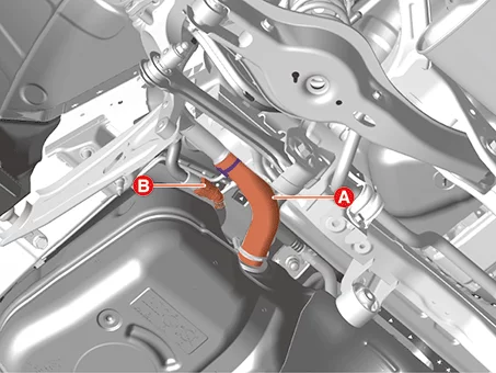
| 4. |
Remove the leveling hose (A).
|
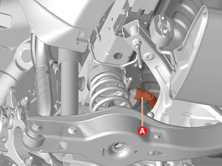
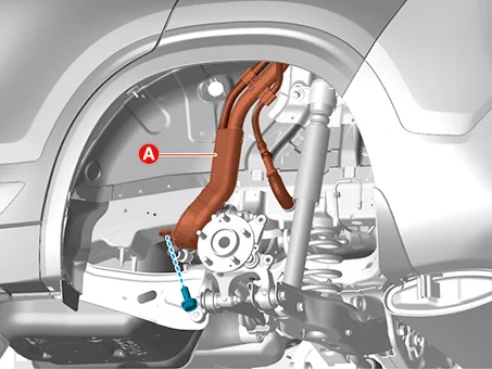
| 5. |
Remove the filler-neck assembly (A) after removing the bolt.
|
| Installation |
| 1. |
Install in reverse order of removal.
|
Fuel Filter Components and Components Location
| Component |
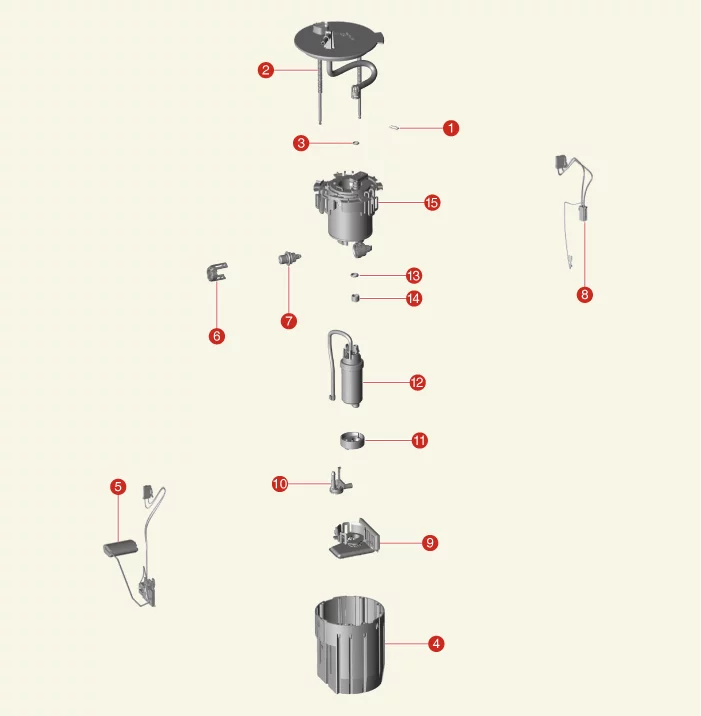
| 1. Clip 2. Fuel Pump Plate Cover Assembly 3. O-Ring 4. Reservoir Cup 5. Fuel Sender Assembly 6. Fuel Pressure Regulator Clip 7. Fuel Pressure Regulator 8. Wiring |
9. Pump Filter 10. Assist Pump 11. Packing 12. Fuel Pump 13. O-ring 14. Spacer 15. Fuel Filter |
Fuel Filter Removal and Installation
| Removal |
| 1. |
Remove the fuel pump module.
(Refer to Fuel Delivery System - "Fuel Pump Module")
|
| 2. |
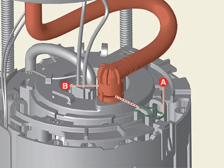
Separate the fuel feed hose connector (B) after removing the clip (A).
|
| 3. |
Disconnect the fuel sender connector (A) and fuel pump connector (B).
|
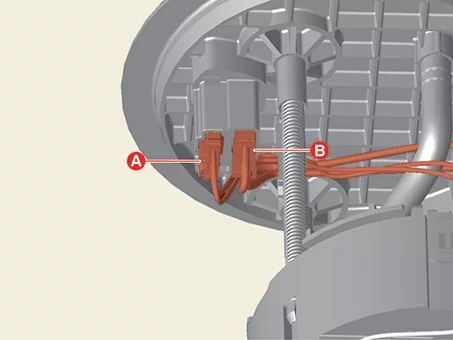
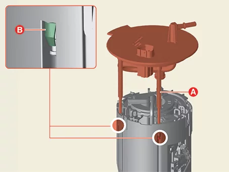
| 4. |
Remove the plate cover assembly (A) by releasing the fixing hook (B).
|
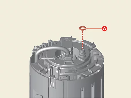
| 5. |
Remove the plate cover O-ring (A).
|
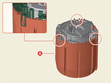
| 6. |
Remove the reservoir cup (A) by releasing the fixing hooks.
|
| 7. |
Remove the fuel pressure regulator clip (A) by releasing the fixing hooks.
|
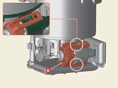
| 8. |
Remove the fuel pressure regulator (A).
|
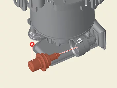
| 9. |
Remove the wiring after disconnecting the fuel pump connectors (A) and ground (B) from the fuel filter.
|
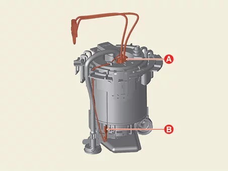
| 10. |
Remove the assist pump (A) by pulling it in the direction of the arrow.
|
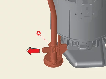
| 11. |
Remove the pump filter (A) by releasing the fixing clips.
|
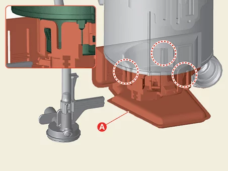
| 12. |
Separate the fuel pump hose (A) by releasing the clamp.
|
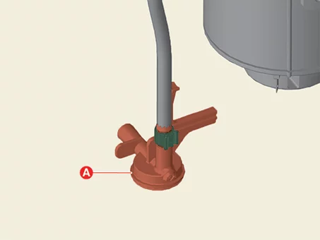
| 13. |
Remove the pump packing (A).
|
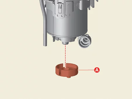
| 14. |
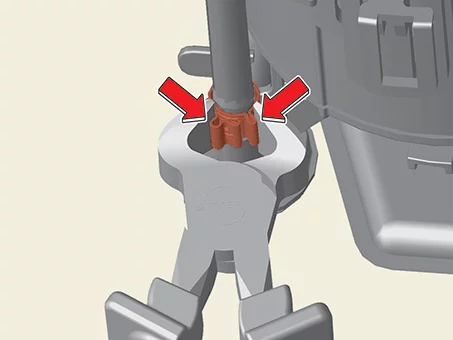
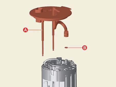
Remove the O-ring (B) and spacer (C) after removing the fuel pump & tube (A).
|
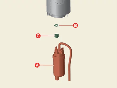
| Installation |
| 1. |
Install in reverse order of removal.
|
| 2. |
Check for fuel leaks after installation.
|
Fuel Line Components and Components Location
| Component Location |
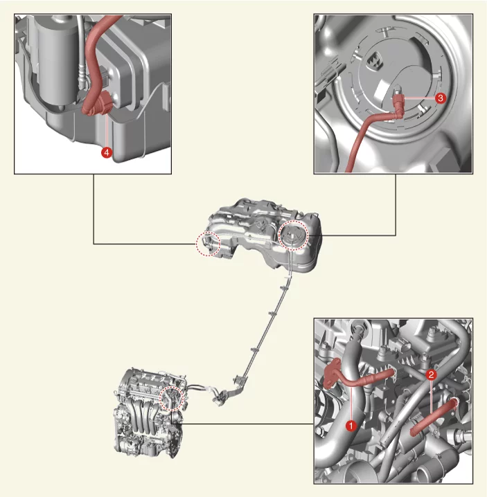
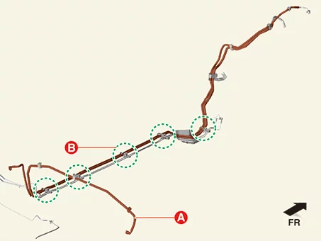
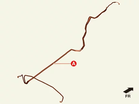
| 1. Fuel Feed Tube (Engine Side) 2. Vapor Tube (Engine Side) |
3. Fuel Feed Tube (Fuel Tank Side) 4. Vapor Tube (Canister Side) |
Fuel Line Removal and Installation
| Removal |
Since there is a risk of injury due to high pressure fuel leakage, do not perform any work right after
the engine is stopped.
|
Cover the connection with a clean cloth since the residual fuel may be released after "Release Residual
Pressure in Fuel Line" procedures.
|
| 1. |
Release the residual pressure in fuel line.
(Refer to Fuel Delivery System - "Release Residual Pressure in Fuel
Line")
|
| 2. |
Disconnect the battery negative ( - ) terminal.
|
| 3. |
Remove the engine cover.
(Refer to Engine Mechanical System - "Engine Cover")
|
| 4. |
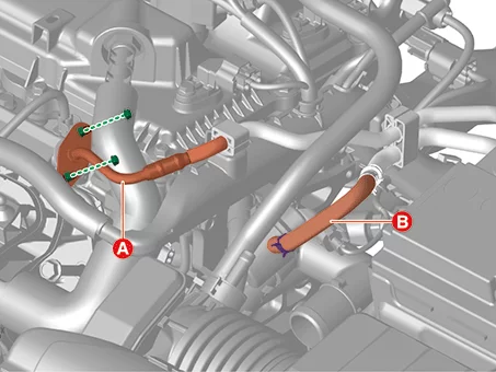
Remove the fuel feed tube (A) and vapor hose (B).
|
| 5. |
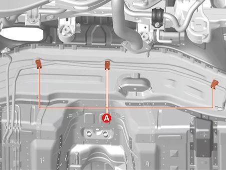
Remove the fuel line holders (A).
|
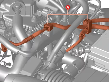
| 6. |
Remove the floor under cover (A).
|
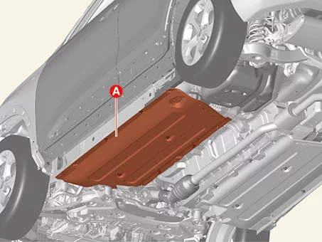
| 7. |
Remove the heat protector (A).
|
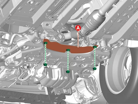
| 8. |
Remove the fuel line protector (A).
|
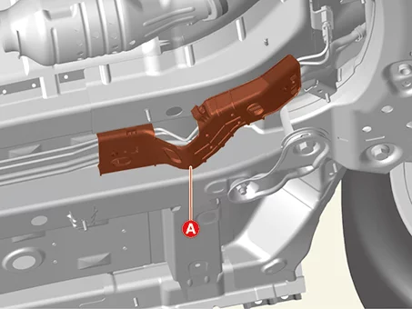
| 9. |
Remove the fuel tank.
(Refer to Fuel Delivery System - "Fuel Tank")
|
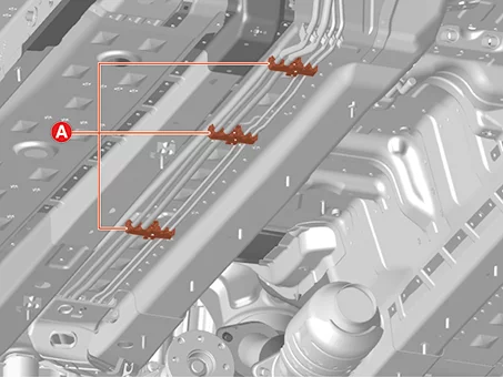
| 10. |
Remove the fuel line holders (A).
|
| 11. |
Separate the fuel line (A) from the holder (B).
|
| Installation |
| 1. |
Install in reverse order of removal.
|
| 2. |
Check for fuel leaks after installation.
|
Fuel Pressure Regulator Components and Components Location
| Component |
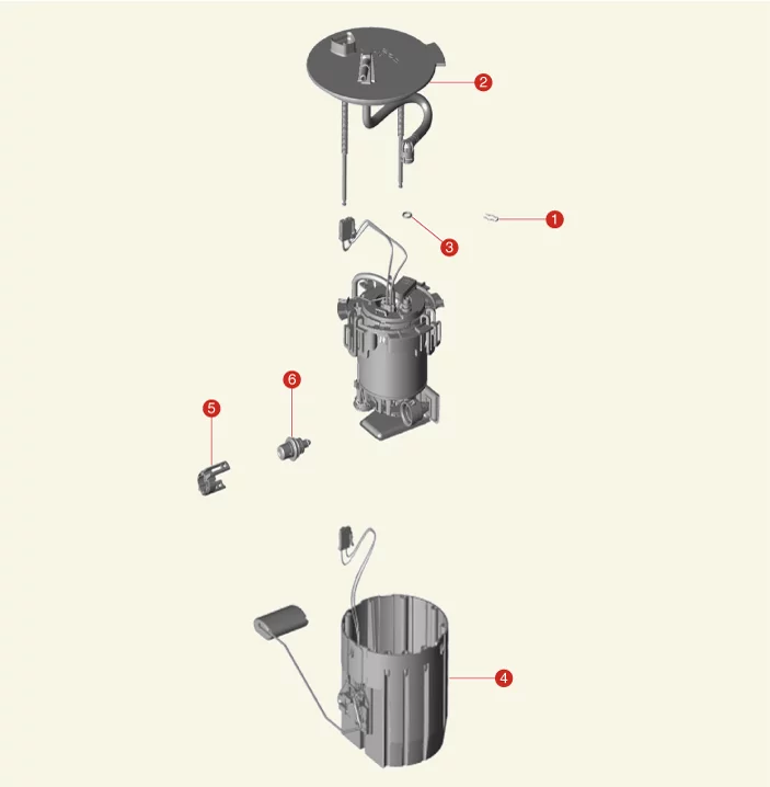
| 1. Clip 2. Fuel Pump Plate Cover Assembly 3. O-Ring |
4. Reservoir Cup 5. Fuel Pressure Regulator Clip 6. Fuel Pressure Regulator |
Fuel Pressure Regulator Removal and Installation
| Removal |
| 1. |
Remove the fuel pump module.
(Refer to Fuel Delivery System - "Fuel Pump Module")
|
| 2. |
Separate the fuel feed hose connector (B) after removing the clip (A).
|
| 3. |
Disconnect the fuel sender connector (A) and fuel pump connector (B).
|
| 4. |
Remove the plate cover assembly (A) by releasing the fixing hook (B).
|
| 5. |
Remove the plate cover O-ring (A).
|
| 6. |
Remove the reservoir cup (A) by releasing the fixing hooks.
|
| 7. |
Remove the fuel pressure regulator clip (A) by releasing the fixing hooks.
|
| 8. |
Remove the fuel pressure regulator (A).
|
| Installation |
| 1. |
Install in reverse order of removal.
|
| 2. |
Check for fuel leaks after installation.
|
Fuel Pump Components and Components Location
| Component |
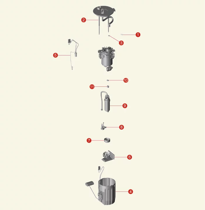
| 1. Clip 2. Fuel Pump Plate Cover Assembly 3. O-Ring 4. Reservoir Cup 5. Wiring 6. Pump Filter |
7. Packing 8. Assist Pump 9. Fuel Pump 10. O-ring 11. Spacer |
Fuel Pump Removal and Installation
| Removal |
| 1. |
Remove the fuel pump module.
(Refer to Fuel Delivery System - "Fuel Pump Module")
|
| 2. |
Separate the fuel feed hose connector (B) after removing the clip (A).
|
| 3. |
Disconnect the fuel sender connector (A) and fuel pump connector (B).
|
| 4. |
Remove the plate cover assembly (A) by releasing the fixing hook (B).
|
| 5. |
Remove the plate cover O-ring (A).
|
| 6. |
Remove the reservoir cup (A) by releasing the fixing hooks.
|
| 7. |
Remove the wiring after disconnecting the fuel pump connectors (A) and ground (B) from the fuel filter.
|
| 8. |
Remove the assist pump (A) by pulling it in the direction of the arrow.
|
| 9. |
Remove the pump filter (A) by releasing the fixing clips.
|
| 10. |
Separate the fuel pump hose (A) by releasing the clamp.
|
| 11. |
Remove the pump packing (A).
|
| 12. |
Remove the O-ring (B) and spacer (C) after removing the fuel pump & tube (A).
|
| Installation |
| 1. |
Install in reverse order of removal.
|
| 2. |
Check for fuel leaks after installation.
|
Fuel Pump Module Specification
| Specification |
|
Item |
Specification |
|
Voltage (V) |
12 |
|
Operating temperature [°C (°F)] |
-40 to 90 (-40 to 194) |
|
Operating current (A) |
Maximum 6.0 |
|
Fuel pressure [kPa (kgf / cm², psi)] |
350 (3.56, 50.76) |
Fuel Pump Module Components and Components Location
| Component |
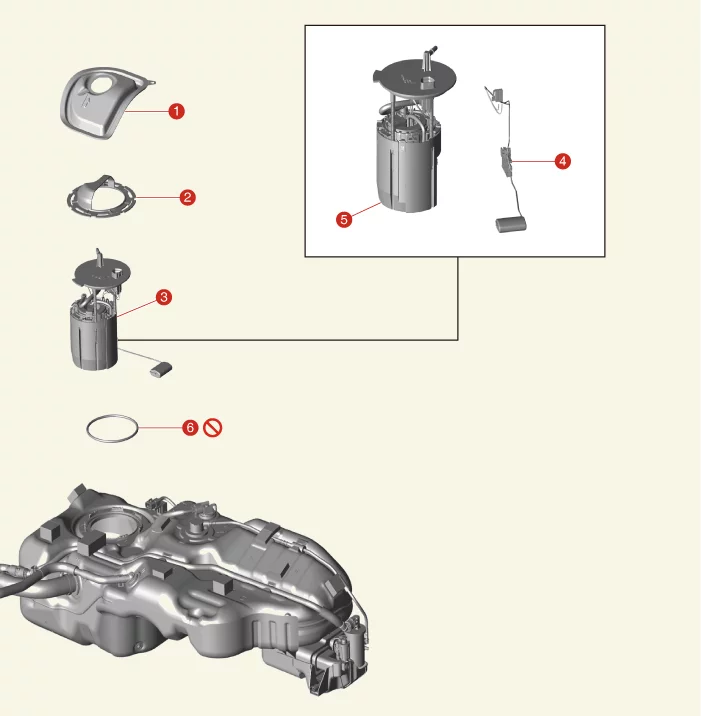
| 1. Service Cover 2. Plate Cover 3. Fuel Pump Module |
4. Fuel Sender Assembly 5. Fuel Pump Assembly 6. O-ring |
Fuel Pump Module On Vehicle Inspection
| On Vehicle Inspection |
| 1. |
The fuel delivery system can be more quickly diagnosed for problems by using the KDS (Refer to "DTC
guide").
|

| Component Inspection |
| 1. |
Remove the rear seat cushion.
(Refer to Body - "Rear Seat Assembly")
|
| 2. |
Remove the fuel pump service cover (A).
|
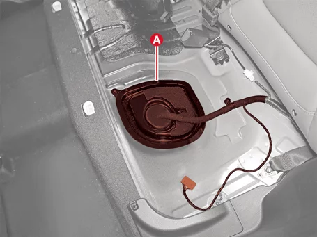
| 3. |
Disconnect the fuel pump module connector (A).
|
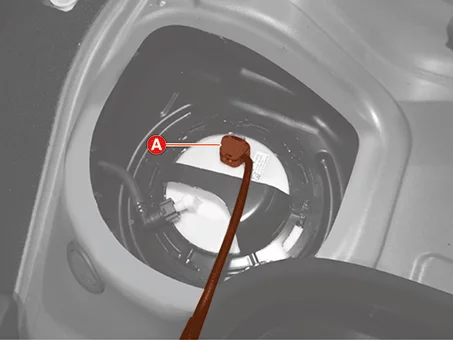
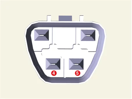
| 4. |
Check the fuel pump operation.
|
Fuel Pump Module Removal and Installation
| Special Service Tool |
|
Tool Name / Number |
Illustration |
Description |
|
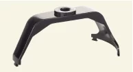
Low Fuel Pump Plate Cover Remover 09310 - B8100 |
|
Used for removing / installing the low pressure fuel pump plate cover |
| Removal |
Cover the connection with a clean cloth since the residual fuel may be released after "Release Residual
Pressure in Fuel Line" procedures.
|
| 1. |
Release the residual pressure in fuel line.
(Refer to Fuel Delivery System - "Release Residual Pressure in Fuel
Line")
|
| 2. |
Disconnect the battery negative ( - ) terminal.
|
| 3. |
Remove the rear seat cushion.
(Refer to Body - "Rear Seat Assembly")
|
| 4. |
Remove the fuel pump service cover (A).
|
| 5. |
Disconnect the fuel pump module connector (A).
|
| 6. |
Separate the fuel feed tube (A).
|
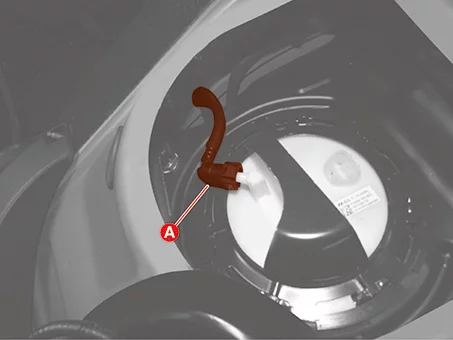
| 7. |
Remove the plate cover by using the SST (09310 - B8100).
Proper Use of SST and Safe Working Posture for Removing the Tightly Fastened Plate Cover (Play ▶)

Notes When Refering Video
This video helps recognize potential hazards in advance and ensures procedures are performed correctly
when safety precautions are required or when failure to follow steps or procedural errors could affect
driving safety.
|
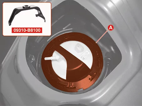

| 8. |
Remove the fuel pump module (A) from the fuel tank.
|
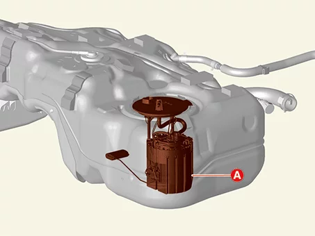
| Installation |
| 1. |
Install in reverse order of removal.
|
| 2. |
Check for fuel leaks after installation.
|
Fuel Sender Specification
| Specification |
|
Floating Position |
Resistance (Ω) |
Capacity [ℓ (U.S gal., U.S.qt., Imp.qt.)] |
|
Full |
14 - 16 |
47.5 (12.55, 50.19, 41.80) |
|
1/2 |
85.5 - 87.5 |
25.6 (6.76, 27.05, 22.53) |
|
Empty |
298 - 305 |
4.0 (1.06, 4.23, 3.52) |
Fuel Sender Components and Components Location
| Component Location |
| 1. Service Cover 2. Plate Cover 3. Fuel Pump Module |
4. Fuel Sender Assembly 5. Fuel Pump Assembly 6. O-ring |
Fuel Sender On Vehicle Inspection
| On Vehicle Inspection |
| 1. |
Remove the rear seat cushion.
(Refer to Body - "Rear Seat Assembly")
|
| 2. |
Remove the fuel pump service cover (A).
|
| 3. |
Disconnect the fuel pump module connector (A).
|
| 4. |
Put the float of the fuel sender at the top and bottom positions and measure the resistance.
|
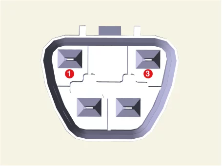
Fuel Sender Removal and Installation
| Removal |
| 1. |
Remove the fuel pump module.
(Refer to Fuel Delivery System - "Fuel Pump Module")
|
| 2. |
Disconnect the fuel sender connector (A).
|
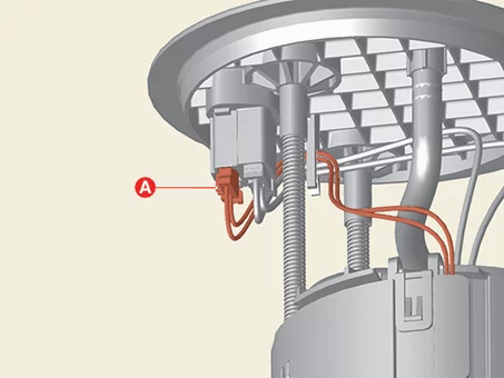
| 3. |
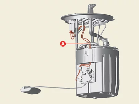
Remove the fuel sender wiring (A) from the fuel pump module.
|
| 4. |
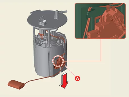
Remove the fuel sender assembly (A) after releasing the fixing hook by pressing it in the direction of
the arrow.
|
| Installation |
| 1. |
Install in reverse order of removal.
|
| 2. |
Check for fuel leaks after installation.
|
Fuel Tank Specification
| Specification |
|
Item |
Specification |
|
Capacity [ℓ (U.S gal., U.S.qt., Imp.qt.)] |
50 (13.21, 52.83, 43.99) |
Fuel Tank Components and Components Location
| Component |
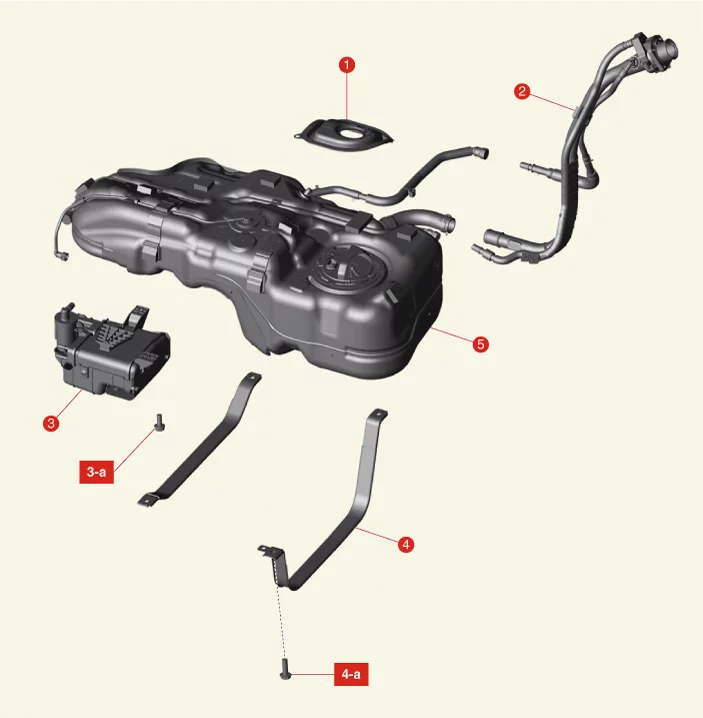
| 1. Service Cover 2. Filler-Neck Assembly 3. Canister 3-a. 3.9 - 5.9 N·m (0.4 - 0.6 kgf·m, 2.9 - 4.3 lb·ft, 34.7 - 52.1 lb·in) |
4. Fuel Tank Band 4-a. 39.2 - 53.9 N·m (4.0 - 5.5 kgf·m, 28.9 - 39.8 lb·ft) 5. Fuel Tank |
Fuel Tank Removal and Installation
| Removal |
Cover the connection with a clean cloth since the residual fuel may be released after "Release Residual
Pressure in Fuel Line" procedures.
|
| 1. |
Release the residual pressure in fuel line.
(Refer to Fuel Delivery System - "Release Residual Pressure in Fuel
Line")
|
| 2. |
Disconnect the battery negative ( - ) terminal.
|
| 3. |
Remove the rear seat cushion.
(Refer to Body - "Rear Seat Assembly")
|
| 4. |
Remove the fuel pump service cover (A).
|
| 5. |
Disconnect the fuel pump module connector (A).
|
| 6. |
Separate the fuel feed tube (A).
|
| 7. |
Remove the center muffler assembly.
(Refer to Engine Mechanical System - "Muffler")
|
| 8. |
Remove the propeller shaft assembly. [4WD Type]
(Refer to All Wheel Drive (AWD) System - "Propeller Shaft")
|
| 9. |
Remove the canister.
(Refer to Emission Control System - "Canister")
|
| 10. |
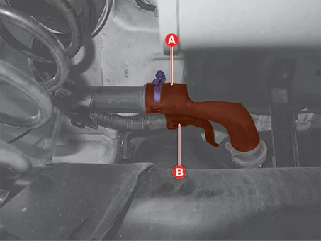
Remove the fuel feed hose (A) and ventilation hose (B).
|
| 11. |
Remove the leveling hose (A).
|
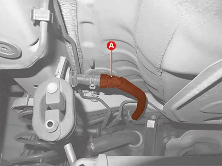
| 12. |
Support the fuel tank securely using the jacks (A).
|
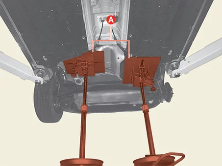
| 13. |
Remove the fuel tank bands (A) after removing the bolts.
|
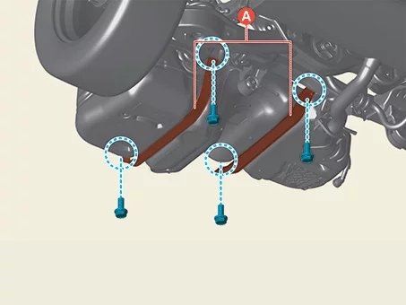
| 14. |
Remove the fuel tank (A).
|
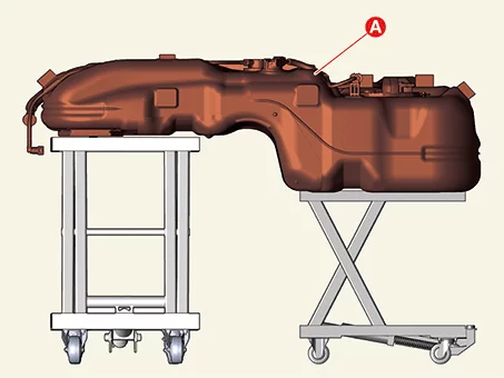
| Installation |
| 1. |
Install in reverse order of removal.
|
| 2. |
Check for fuel leaks after installation.
|
Injector Specification
| Specification |
|
Item |
Specification |
|
Coil resistance (Ω) |
14.5 [20°C (68°F)] |
Injector Components and Components Location
| Component Location |
| 1. Delivery Pipe & Injector 1-a. 8.8 - 11.8 N·m (0.9 - 1.2 kgf·m, 6.5 - 8.7 lb·ft) 1-b. 18.6 - 23.5 N·m (1.9 - 2.4 kgf·m, 13.7 - 17.4 lb·ft) |
2. Clip 3. Injector 4. O-ring 5. Delivery Pipe |
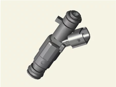
Injector Description and Operation
| Description |
| • |
Injector is an electronically controlled fuel injection device that is a solenoid valve that supplies
accurately calculated fuel to the engine in the form of spray for optimal combustion for various engine
operating conditions.
|
| • |
Engine Control Module (ECM) controls the amount of fuel injection to meet the air-fuel ratio (AFR)
required by the engine control system by measuring the air-fuel ratio of intake air volume and exhaust gas
and adjusting the injector operating time to improve fuel efficiency, engine performance and reduce the
exhaust gas.
|
Injector On Vehicle Inspection
| On Vehicle Inspection |
| 1. |
The fuel delivery system can be more quickly diagnosed for problems by using the KDS (Refer to "DTC
guide").
|
| Component Inspection |
| 1. |
Turn the IG OFF.
|
| 2. |
Disconnect the injector connector (A).
|
| 1. |
Measure resistance between the injector terminals 1 and 2.
|
| 2. |
Check that the resistance is within the specification.
|
Injector Removal and Installation
| Removal |
| 1. |
Remove the injector from the delivery pipe.
(Refer to Fuel Delivery System - "Delivery Pipe")
|
| Installation |
| 1. |
Install in reverse order of removal.
|


Other information:
Kia Seltos SP2 (2021-2026) Service Manual: Navigation-based Smart Cruise Control (NSCC)
Navigation-based Smart Cruise Control (NSCC) in the Kia Seltos can help maintain an appropriate driving speed according to road conditions when driving on highways or motorways. While Smart Cruise Control is operating, NSCC uses road information from the navigation system to support smoother and safer highway driving. NOTICE NSCC is available only on controlled-access roads of certain highways.Kia Seltos SP2 (2021-2026) Service Manual: Vehicle load limit
The vehicle load limit for the Kia Seltos is shown on the tire and loading information label located on the driver's door area. Tire and loading information label The label on the driver's door sill shows the original tire size, the recommended cold tire pressures, the maximum number of occupants, and the vehicle capacity weight for your Kia Seltos.