
Kia Seltos SP2 (2021-2026) Service Manual / Engine Control / Fuel System / ISG (Idle Stop & Go) System
Kia Seltos: Engine Control / Fuel System / ISG (Idle Stop & Go) System
Contents:
- Description and Operation
- Inspection
- ISG OFF switch Removal and Installation
- ISG OFF switch Inspection
- DC/DC Converter Specifications
- DC/DC Converter Description and Operation
- DC/DC Converter Removal and Installation
Description and Operation
| Description |
| • |
ISG system improves fuel efficiency and reduces emissions by temporary stop the vehicle engine either at
waiting for a traffic signal or stopping.
|
| • |
The ISG system is always ON whenever the engine start.
|
| • |
If the vehicle is completely stopped while the brake pedal is pressed, the engine will automatically stop
and the AUTO STOP indicator (green) ON.
|
| • |
If you release your foot from the brake pedal while the engine is automatically stopped, the engine will
restart and the AUTO STOP indicator will OFF.
During AUTO HOLD operation, the engine remains stopped even if you release the brake pedal. When you
press the accelerator pedal, the engine will restart.
|
| System Components |
The ISG system consists of a mutual network among the related components. Refer to relevant system manual
for detail.
(Refer to table below)
|

|
Component |
System |
|
ECM |
Engine Control / Fuel System - Engine Control Module (ECM) |
|
Seat belt switch |
Restraint - Seat Belt Buckle Switch (BS) |
|
Door switch |
Body Electrical System - Keyless Entry And Burglar Alarm |
|
Hood switch |
Body Electrical System - Keyless Entry And Burglar Alarm |
|
Brake switch |
Brake System - Brake Switch |
|
Brake booster vacuum pressure sensor |
Brake System - Brake Booster |
|
Ambient temperature sensor |
Heating, Ventilation And Air Conditioning - Ambient Temperature Sensor |
|
Battery sensor |
Engine Electrical System - Battery Sensor |
|
AGM battery |
Engine Electrical System - Battery |
|
DC DC converter |
Engine Electrical System - DC DC converter |
|
Starter |
Engine Electrical System - Starter |
|
Position switch |
Automatic Transaxle System - Position Switch |
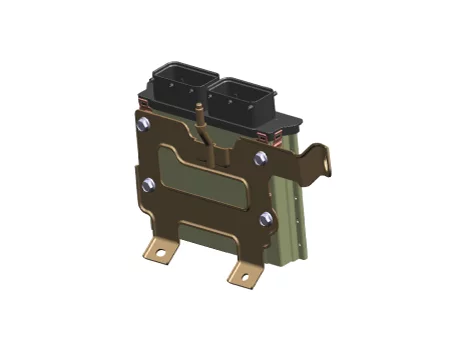
| • |
ECM : Using all vehicle control system information, the ECM
controls the Engine ON and OFF.
|
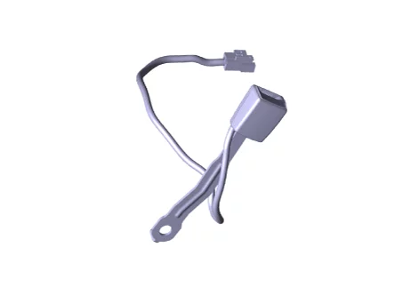
| • |
Seat belt switch : It detects the seat belt engagement and this
information is used as the ISG system operating condition.
|
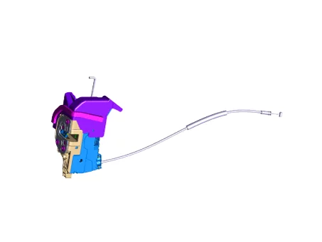
| • |
Door switch : It detects the driver side door open/close status
and this information is used as the ISG system operating condition.
|
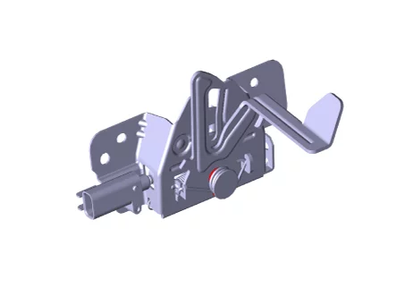
| • |
Hood switch : It detects the hood open/close status and this
information is used as the ISG system operating condition.
|
| • |
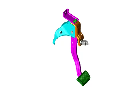
Brake switch : It detects the brake pedal operation and this
information is used as the ISG system operating condition.
|
| • |
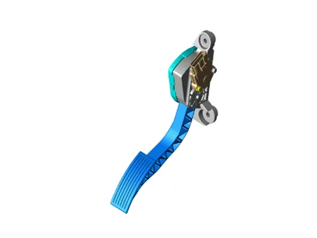
Accelerator position sensor : It detects the accelerator pedal
operation and this information is used as the ISG system operating condition.
|
| • |
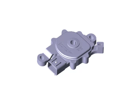
Position switch : It detects the gear shift position (P/R/N/D,
manual mode) and this information is used as the ISG system operating condition.
|
| • |
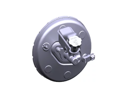
Brake booster vacuum pressure sensor : It detects the brake
pressure and this information is used as the ISG system operating condition.
|
| • |
Ambient temperature sensor : It detects the ambient temperature
and this information is used as the ISG system operating condition.
|
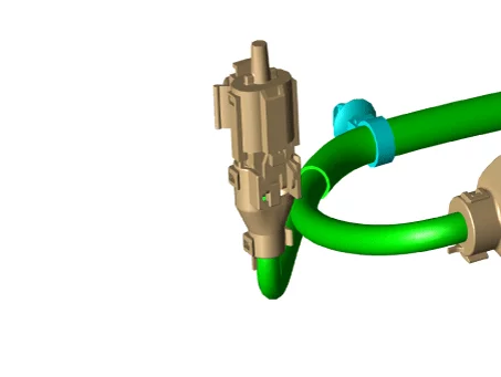
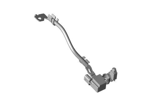
| • |
Battery sensor : If the battery sensor is deactivated, the ISG
system does not work.
|
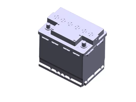
| • |
AGM battery : Due to more frequent engine start ON and OFF process
than regular vehicles, the vehicles with ISG require the higher battery performance and the better battery
state of charge management. Despite the high loads by frequent charging and discharging, AGM battery
presents excellent durability.
|
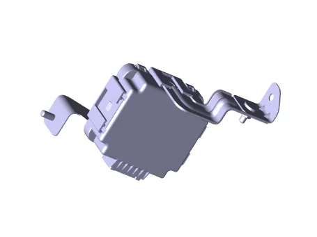
| • |
DC/DC converter : The DC converter supplies the boosted voltage
(12 ± 0.5V) to prevent electronic device (AVN or Audio, Cluster, etc.) reset from voltage drop at engine
automatic start.
|
| • |
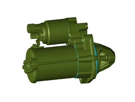
Starter : Vehicles with ISG are frequently engine ON/OFF,
therefore starter motor with improved durability is applied.
|
| • |
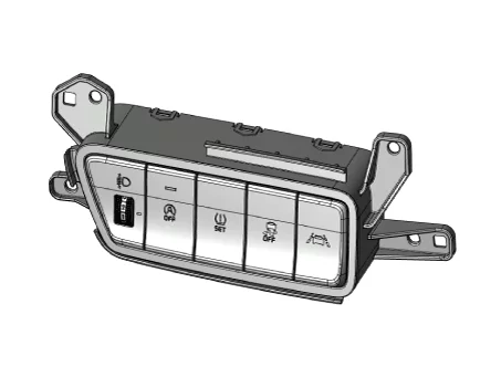
ISG OFF switch : The ISG system is always ON whenever the engine
starts, and can ISG system OFF by pressing the switch.
|
| System Operating Condition |
|
Division |
Item |
Condition |
||
| Auto start & Auto stop |
Driver condition |
ISG OFF switch |
OFF |
|
| Switch (Seat belt/Door/Hood) |
Fastened/Closed/Closed |
|||
| Gear position |
D/N |
|||
| Pedal condition (Brake/Clutch) |
Brake condition ON (Auto stop) / OFF (Auto start) |
|||
| Vehicle speed |
Entering 0 kph after driving over 5 kph (3.1 mph). |
|||
| Climate control system condition |
FATC/MTC Satisfied |
|||
| MPDS |
Less than 180 degrees |
|||
|
Battery condition |
Charge/Discharge performance |
SOC > 68 % |
||
| Engine coolant temperature |
20 - 43 °C (68 -109.4°F) |
|||
| Ambient air temperature |
Ambient air temperature : -20 to 50°C (-4 to 122°F) |
|||
| Atmospheric pressure |
More than 750 hPa (75 kph, 0.76 kg/cm², 10.88 psi) |
|||
| Brake vacuum pressure |
Less than -35 kpa (-0.36 kg/cm², -5.07 psi) |
|||
| Incline condition |
-5 to 12% |
|||
| ECU, TCU condition |
Condition (temperature, error, OBD diagnosis) satisfied |
|||
| ISG related error |
None |
|||
| Forced restart |
Climate control system condition |
Blower MAX. / Front Defogger |
ON |
|
|
Battery condition |
Voltage |
Insufficient charging and discharging performance |
||
| Safety |
Brake vacuum pressure |
More than -35 kpa (-0.36 kg/cm², -5.07 psi) |
||
| Vehicle speed |
More than 1.5 kph (0.9 mph) |
|||
| Switch |
Seat belt/Door |
Open during brake pedal ON |
||
|
Hood open |
Start by using the key (Message appear on instrument cluster) |
|||
| Brake/Accel pedal ON at the same time |
Immediately restart |
|||
| ISG OFF switch |
Immediately restart |
|||
Inspection
| Inspection |
|
ISG OFF switch Removal and Installation
| Removal |
| 1. |
Remove the side crash pad switch.
(Refer to Body Electrical System - "Headlamp Leveling Switch")
|
| Installation |
| 1. |
Install in the reverse order of removal.
|
ISG OFF switch Inspection
| Inspection |
| 1. |
Remove the side crash pad switch.
|
| 2. |
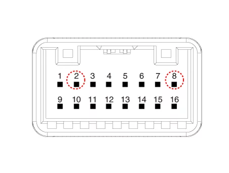
After pushing the ISG OFF switch, check for continuity between the ground (pin 8) and signal (pin 2).
|
DC/DC Converter Specifications
| Specification |
[200W]
|
Item |
Specification |
|
Input voltage range (V) |
7 - 16 |
|
Battery power supply (B+) output voltage (V) |
11.4 - 12.6 |
|
ACC output voltage (V) |
11 - 13 |
DC/DC Converter Description and Operation
| Description |
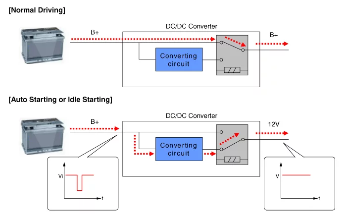
Due to the considerably more frequent occurrence of starting operations, the electrical load that occurs often
leads to voltage dips in the vehicle network. In order to stabilize the power supply for certain voltage-sensitive
electrical components, a DC/DC converter is used in conjunction with the ISG function. The DC/DC converter supplies
the relay with a voltage that also remains constant during the starting operation.
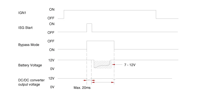
The DC/DC converter is fitted at the behind of the glove box. Via the test leads for input voltage and the start
relay , the electronics decide whether the power is supplied to the output via the bypass or the DC/DC converter. In
the bypass mode, the on-board supply voltage is not fed across the DC/DC converter, rather is transferred directly
to the outputs. In the booster phase, the vehicle voltage is adapted.
| Operation |
DC/DC Converter Removal and Installation
| Removal |
| 1. |
Disconnect the battery negative (-) terminal.
|
| 2. |
Remove the crash pad lower panel.
(Refer to Body "Crash Pad Lower Panel")
|
| 3. |
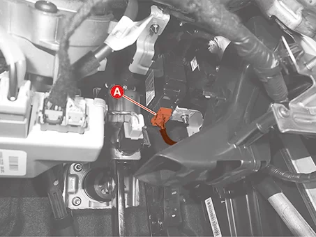
Disconnect the DC/DC converter connector (A).
|
| 4. |
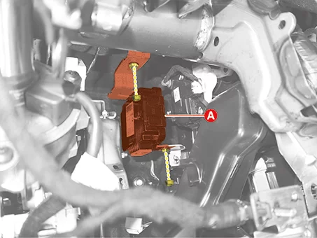
Remove the DC/DC converter (A) after removing the nuts.
|
| Installation |
| 1. |
Install in the reverse order of removal.
|


