
Kia Seltos: Heating,Ventilation And Air Conditioning / Heater
Contents:
- Components and Components Location
- On Vehicle Inspection
- Heater Unit Removal and Installation
- Heater Core Removal and Installation
- Evaporator Core Removal and Installation
- Temperature Control Actuator Description and Operation
- Temperature Control Actuator Removal and Installation
- Temperature Control Actuator Inspection
- Mode Control Actuator Description and Operation
- Mode Control Actuator Removal and Installation
- Mode Control Actuator Inspection
- Auto defogging Actuator Description and Operation
- Auto defogging Actuator Removal and Installation
- Auto defogging Actuator Inspection
Components and Components Location
| Component |
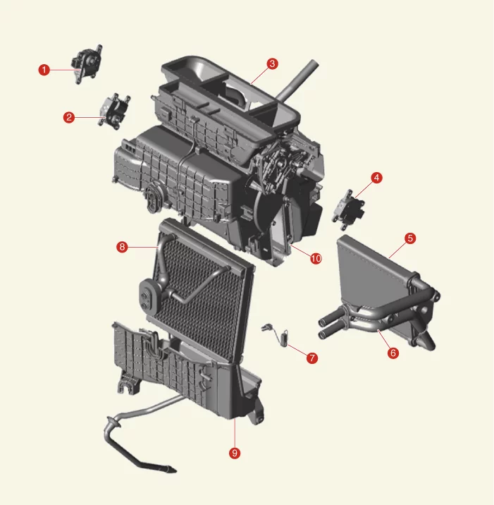
| 1. Auto Defogging Actuator 2. Temperature Control Actuator 3. Heater Unit 4. Mode Control Actuator 5. Heater Core |
6. Heater Core Cover 7. Evaporator Temperature Sensor 8. Evaporator Core 9. Heater Unit Lower Cover 10. PTC Heater |
On Vehicle Inspection
| On Vehicle Inspection |
| Diagnosis with KDS |
| 1. |
The heating,ventilation and air conditioning system can be more quickly diagnosed for problems with the
KDS (Refer to "DTC guide").
|

Heater Unit Removal and Installation
| Removal |
| 1. |
Recover the refrigerant by using recovery/recycling/charging equipment.
(Refer to Air conditioning System - "Refrigerant
Recovery/Recycling/Charging/Vacuum/Leak Test")
|
| 2. |
When the engine is cooled, drain the engine coolant from the radiator.
(Refer to Engine Mechanical System - "Coolant")
|
| 3. |
Remove the front wiper motor.
(Refer to Body Electrical System - "Wiper Motor")
|
| 4. |
Remove both front seat assembly.
(Refer to Body - "Front Seat Assembly")
|
| 5. |
Remove the floor console assembly.
(Refer to Body - "Floor Console Assembly")
|
| 6. |
Remove the both side front pillar trims.
(Refer to Body - "Front Pillar Trim")
|
| 7. |
Remove both cowl side trims.
(Refer to Body - "Cowl Side Trim")
|
| 8. |
Remove both crash pad side covers.
(Refer to Body - "Crash Pad Side Cover")
|
| 9. |
Separate the MDPS column & housing.
(Refer to Steering System - "MDPS Column & Housing")
|
| 10. |
Remove the expansion valve cover (A) after removing the nut.
|
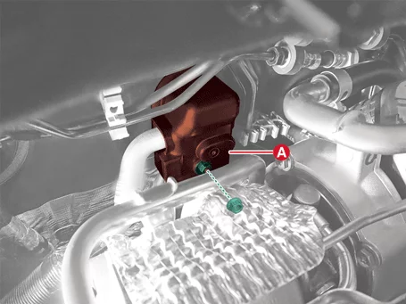
| 11. |
Remove the expansion valve (A) from the evaporator core after removing the bolts.
|
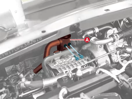
| 12. |
Remove the air cleaner assembly.
(Refer to Engine Mechanical System - "Air Cleaner")
|
| 13. |
Disconnect the electric waste gate actuator connector (A).
|
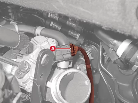
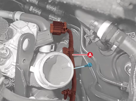
| 14. |
Remove the electric waste gate actuator wiring and bracket (A).
|
| 15. |
Remove the upper heater hose (A).
|
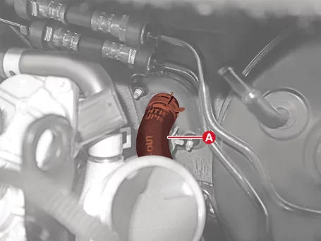

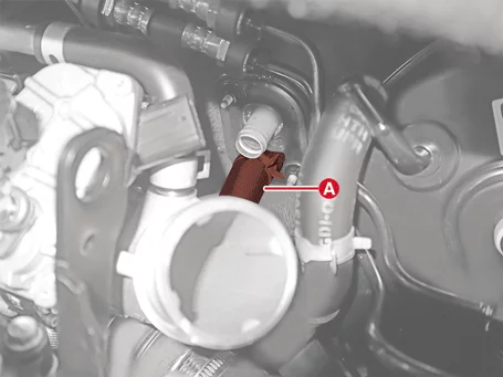
| 16. |
Remove the lower heater hose (A).
|
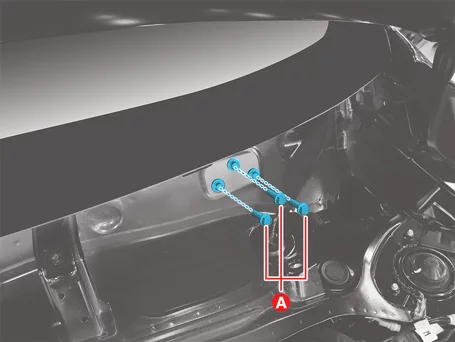
| 17. |
Remove the dash panel cowl cross bar bolts (A).
|
| 18. |
Remove the side panel cowl cross bar bolts (A) after removing hole plug (B).
|
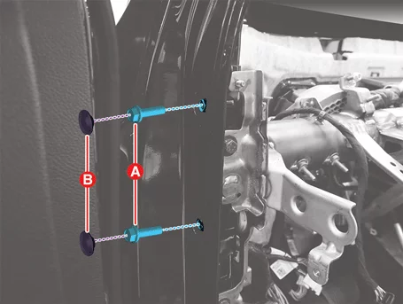
| 19. |
Disconnect the SRSCM connector (A) by releasing the locking pin.
|
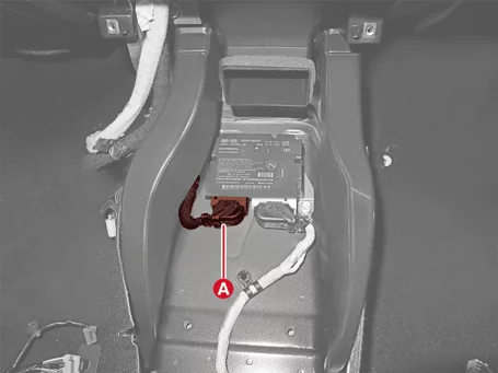
| 20. |
Disconnect the roof antenna connector (A).
|
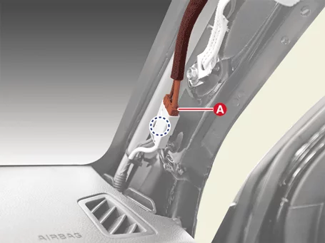

| 21. |
Disconnect the roof trim connector (A).
|
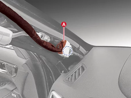
| 22. |
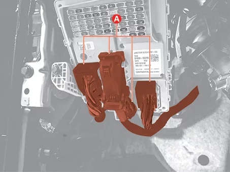
Disconnect the integrated central control unit (ICU) connectors (A).
|
| 23. |
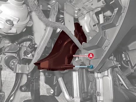
Remove the driver's side shower duct (A) after removing the screw.
|
| 24. |
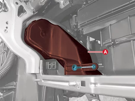
Remove the passenger's side shower duct (A) after removing the screw.
|
| 25. |
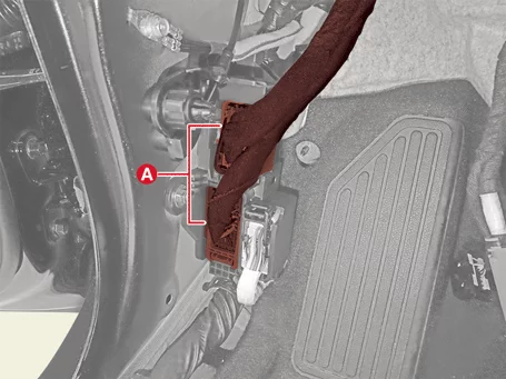
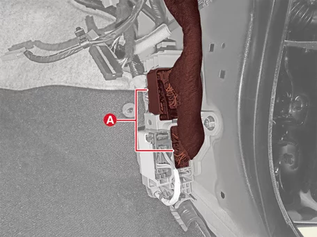
Disconnect the multi-box connectors (A).
[Driver's side]
[Passenger's side]
|
| 26. |
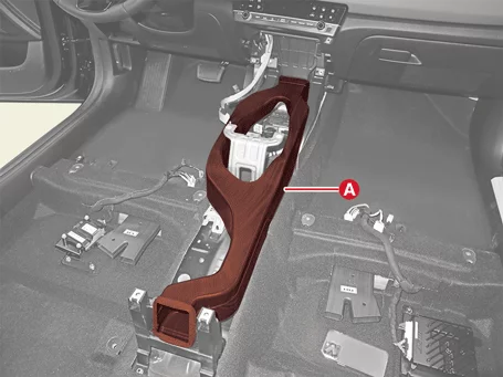
Remove the rear air vent (A).
|
| 27. |
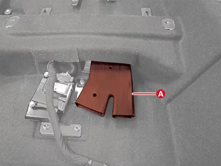
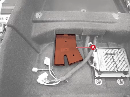
Remove the rear heating duct (A).
[Driver's side]
[Passenger's side]
|
| 28. |
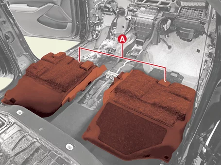
Separate the floor carpet (A) backwards.
|
| 29. |
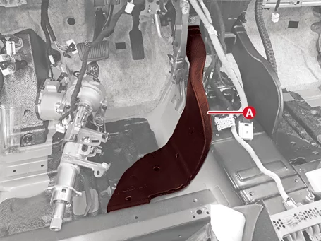
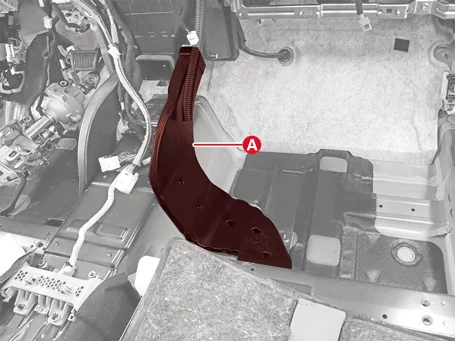
Remove the rear heating duct (A).
[Driver's side]
[Passenger's side]
|
| 30. |
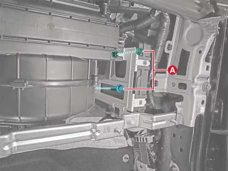
Remove the integrated body control unit (IBU) bolt and nut (A).
|
| 31. |
Separate the drain hose (A).
|
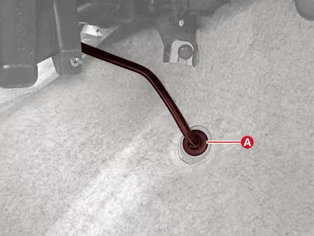
| 32. |
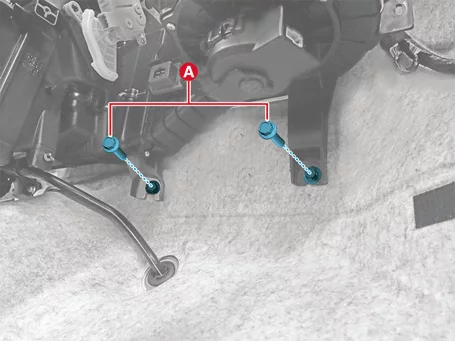
Remove the heater and blower unit lower bolts (A).
|
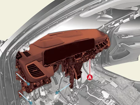
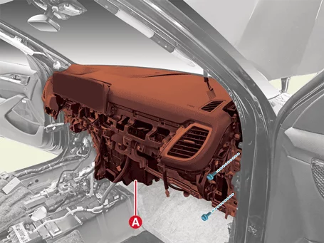
| 33. |
Remove the bolts and remove the crash pad, heater and blower unit (A) from the body at the same time.
[LH]
[RH]
|
| 34. |
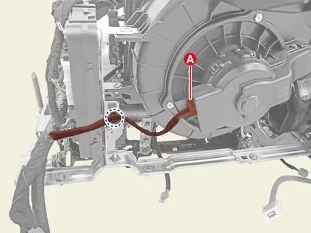
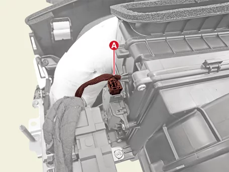
Disconnect the each connector of the heater and blower unit and remove the wiring clips.
[Driver's Side]
[Passenger's Side]
|
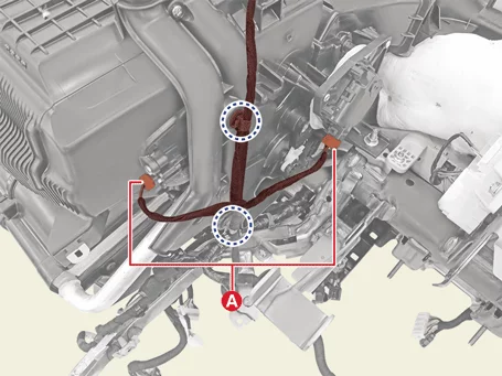
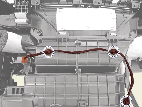
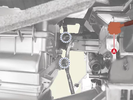
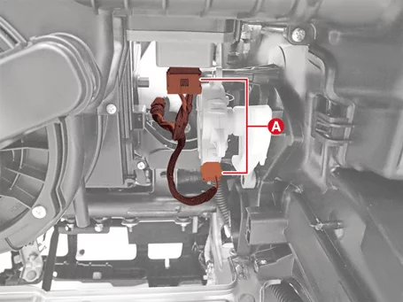
| 35. |
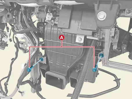
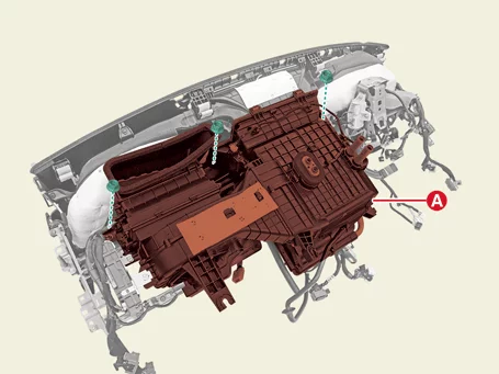
Remove the heater and blower unit.
|
| 36. |
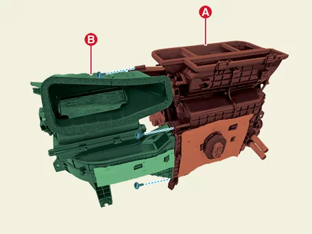
Separate the heater unit (A) and the blower unit (B) after removing the screws.
|
| Installation |
| 1. |
Install in reverse order of removal.
|
Heater Core Removal and Installation
| Removal |
| 1. |
Remove the blower unit from the heater unit.
(Refer to Heater - "Heater Unit")
|
| 2. |
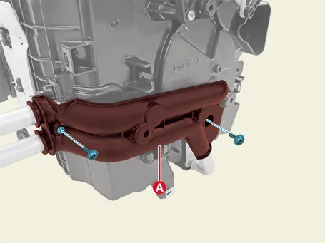
Remove the heater core cover (A) after removing the screws.
|
| 3. |
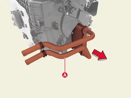
Remove the heater core (A) in the direction of the arrow.
|
| Installation |
| 1. |
Install in reverse order of removal.
|
Evaporator Core Removal and Installation
| Removal |
| 1. |
Remove the blower unit from the heater unit.
(Refer to Heater - "Heater Unit")
|
| 2. |
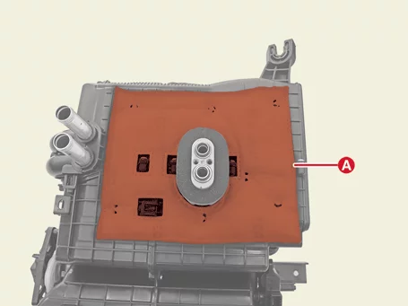
Remove the heater unit pad (A).
|
| 3. |
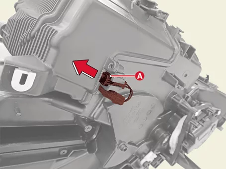
Separate the evaporator temperature sensor (A) in the direction of the arrow.
|
| 4. |
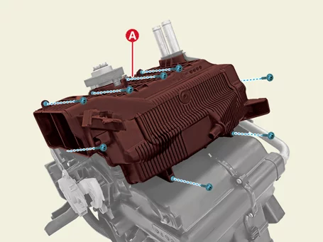
Remove the evaporator core cover (A) after removing the screws.
|
| 5. |
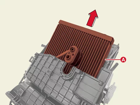
Remove the evaporator core (A) in the direction of the arrow.
|
| Installation |
| 1. |
Install in reverse order of removal.
|
Temperature Control Actuator Description and Operation
| Description |
| • |
The heater unit is equipped with a mode actuator and a temperature control actuator.
|
| • |
It is operated by a control switch and controls the position of the temperature control door to adjust
the temperature of the discharge air.
|
Temperature Control Actuator Removal and Installation
| Removal |
| 1. |
Remove the crash pad center panel.
(Refer to Body - "Crash Pad Lower Panel")
|
| 2. |
Remove the passenger's side shower duct (A) after removing the screw.
|
| 3. |
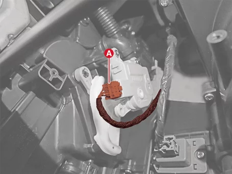
Disconnect the temperature control actuator connector (A).
|
| 4. |
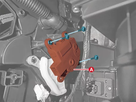
Remove the temperature control actuator (A) after removing the screws.
|
| Installation |
| 1. |
Install in reverse order of removal.
|
Temperature Control Actuator Inspection
| Inspection |
| 1. |
Turn the IG OFF.
|
| 2. |
Disconnect the temperature control actuator connector.
|
| 3. |
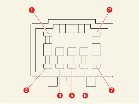
Connect the power ( + ) terminal to the 3 terminal of the actuator connector and the ( - ) terminal to
the 4 terminal and check whether the actuator operates. When connecting in the opposite direction, check if
it operates in reverse.
|
| 4. |
Connect the temperature control actuator connector.
|
| 5. |
Turn the IG ON.
|
| 6. |
Measure the terminal voltage between 6 - 7.
* Feedback the current position of the actuator to the control.
|
| 7. |
If the measured voltage does not match with the specifications, replace it with a new temperature control
actuator.
|
Mode Control Actuator Description and Operation
| Description |
| • |
The mode control actuator installed on the heater unit adjusts the wind direction mode of the air
conditioner according to the input signal to the control panel by the driver.
|
| • |
It consists of an actuator motor that moves the mode door and a potentiometer that detects the position
of the mode door. According to the operation of the control panel, the mode control actuator changes the
wind direction mode in the order of Vent → Bi-Level → Floor → Mix.
|
Mode Control Actuator Removal and Installation
| Removal |
| 1. |
Remove the DC/DC Converter.
(Refer to Engine Control / Fuel System - "DC/DC Converter")
|
| 2. |
Remove the driver's side shower duct (A) after removing the screw.
|
| 3. |
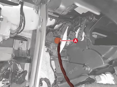
Disconnect the mode control actuator connector (A).
|
| 4. |
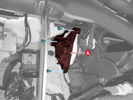
Remove the mode control actuator (A) after removing the screws.
|
| Installation |
| 1. |
Install in reverse order of removal.
|
Mode Control Actuator Inspection
| Inspection |
| 1. |
Turn the IG OFF.
|
| 2. |
Disconnect the mode control actuator connector.
|
| 3. |
Connect the power ( + ) terminal to the terminal 3 of the mode actuator connector and the ( - ) terminal
to the terminal 4 and check whether the motor operates. When connecting in the opposite direction, check if
it operates in reverse.
|
| 4. |
Connect the mode control actuator connector.
|
| 5. |
Turn the IG ON.
|
| 6. |
Measure the terminal voltage between 5 - 6.
* Feedback the current position of the actuator to the control.
|
| 7. |
If the measured voltage does not match with the specifications, replace it with a new mode control
actuator.
|
Auto defogging Actuator Description and Operation
| Description |
Auto defogging Actuator Removal and Installation
| Removal |
| 1. |
Remove the crash pad center panel.
(Refer to Body - "Crash Pad Lower Panel")
|
| 2. |
Remove the passenger's side shower duct (A) after removing the screw.
|
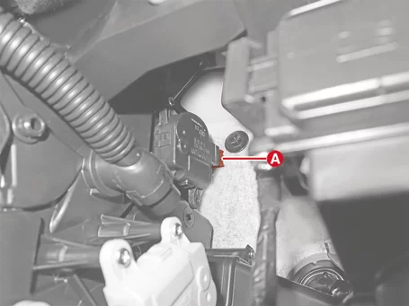
| 3. |
Disconnect the auto defogging actuator connector (A).
|
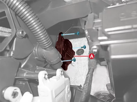
| 4. |
Remove the auto defogging actuator (A) after removing the screws.
|
| Installation |
| 1. |
Install in reverse order of removal.
|
Auto defogging Actuator Inspection
| Inspection |
| 1. |
Turn the IG OFF.
|
| 2. |
Disconnect the auto defogging actuator connector.
|
| 3. |
Connect the power ( + ) terminal to the 3 terminal of the auto defogging actuator connector and the ( - )
terminal to the 4 terminal and check whether the motor is running. When connected in the opposite direction,
check if it operates in reverse.
|
| 4. |
Connect the auto defogging actuator connector.
|
| 5. |
Turn the IG ON.
|
| 6. |
Measure the terminal voltage between 5 - 6.
* Feedback the current position of the actuator to the control.
|
| 7. |
If the measured voltage does not match the specifications, replace it with a new auto defogging actuator.
|


Other information:
Kia Seltos SP2 (2021-2026) Service Manual: Closing the fuel filler door
To install the fuel cap on the Kia Seltos, turn it clockwise until it clicks one time. This click indicates that the cap is securely tightened and properly sealed. Close the fuel filler door and press it lightly to make sure it is fully closed and flush with the body of the vehicle. WARNING Refueling Always remove the fuel cap carefully and slowly.The Kia Seltos light switch includes positions for headlights, position lamps, AUTO lighting, and OFF or DRL OFF operation. To operate the lights, turn the knob at the end of the control lever to one of the following positions: OFF position / DRL off position Auto light position Position & Tail lamp Headlight position