Owner's library Kia Seltos Manuals Owner's manual pages, service notes, maintenance references and practical Kia Seltos help in one clean library.

Kia Seltos reference pages

Manuals, maintenance notes and quick owner help.

Find Kia Seltos operating instructions, warning light explanations, service information and owner guidance without digging through a full PDF.

Kia Seltos: Intelligent Variable Transmission (IVT) / Installation

Special Service Tool
Tool Name / Number
Illustration
Description
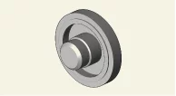
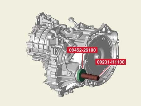
Oil seal installer
09452 - 26100

Intelligent Variable Transmission (IVT) System — Intelligent Variable Transmission (IVT) / Installation / Special Service Tool illustration

Used for IVT transmission case and housing oil seal installation [2WD]
(Used with the handle)
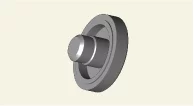
Oil seal installer
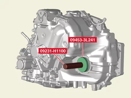
09453 - 3L241

Intelligent Variable Transmission (IVT) System — Intelligent Variable Transmission (IVT) / Installation / Special Service Tool illustration

Used for IVT transmission case oil seal installation [4WD]
(Used with the handle)
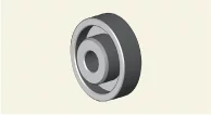
Oil seal installer
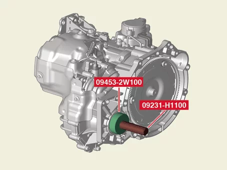
09453 - 2W100

Intelligent Variable Transmission (IVT) System — Intelligent Variable Transmission (IVT) / Installation / Special Service Tool illustration

Used for IVT transmission housing oil seal installation [4WD]
(Used with the handle)
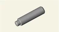
Handle
09231 - H1100

Intelligent Variable Transmission (IVT) System — Intelligent Variable Transmission (IVT) / Installation / Special Service Tool illustration

Used with the oil seal installer

Installation
1.
When ATF leakage occurs due to the damage of the differential oil seal, replace the seal with a new one.
Note    
When installing a new oil seal, use the handle (09231 - H1100) and specified oil seal installer.
2WD
•
IVT transmission case and housing : Oil seal installer (09452 - 26100)

Intelligent Variable Transmission (IVT) System — Intelligent Variable Transmission (IVT) / Installation illustration

4WD
•
IVT transmission case : Oil seal installer (09453 - 3L241)

Intelligent Variable Transmission (IVT) System — Intelligent Variable Transmission (IVT) / Installation illustration

•
IVT transmission housing : Oil seal installer (09453 - 2W100)

Intelligent Variable Transmission (IVT) System — Intelligent Variable Transmission (IVT) / Installation illustration

2.
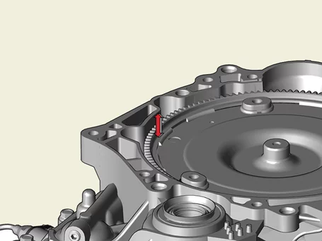
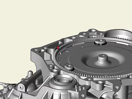
Check that the torque converter is correctly assembled.
(1)
Check the depth from the face of the converter housing to the torque converter with the torque converter is facing up.
[Correct assembly condition]

Intelligent Variable Transmission (IVT) System — Intelligent Variable Transmission (IVT) / Installation illustration

[Incorrect assembly condition]

Intelligent Variable Transmission (IVT) System — Intelligent Variable Transmission (IVT) / Installation illustration

(2)
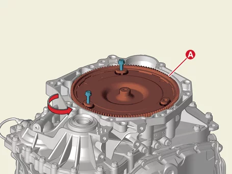
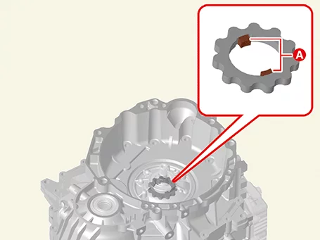
If the torque converter protrudes, rotate the torque converter (A) using IVT mounting bolts to fit into the oil pump key.

Intelligent Variable Transmission (IVT) System — Intelligent Variable Transmission (IVT) / Installation illustration

Note    
•
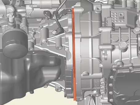
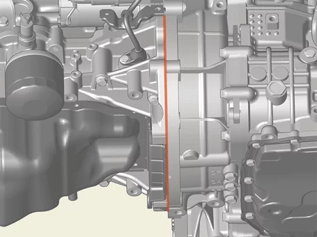
When the torque converter is not normally assembled and the engine and the IVT are combined, a gap occurs between the engine block and the torque converter housing. If a gap occurs, remove the IVT and reassemble the torque converter in accordance with the oil pump key.
Torque converter incorrect assembly

Intelligent Variable Transmission (IVT) System — Intelligent Variable Transmission (IVT) / Installation illustration

Torque converter correct assembly

Intelligent Variable Transmission (IVT) System — Intelligent Variable Transmission (IVT) / Installation illustration

•
If the bolt is tightened while there is a gap, it can cause damage on the key (A) of oil pump gear. In this case, replace the IVT assembly after removing the mounting bolts.

Intelligent Variable Transmission (IVT) System — Intelligent Variable Transmission (IVT) / Installation illustration

3.
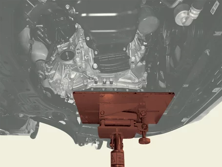
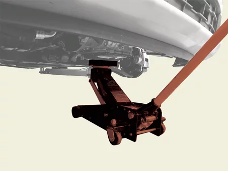
Install the IVT by slowly raising the jack.

Intelligent Variable Transmission (IVT) System — Intelligent Variable Transmission (IVT) / Installation illustration

Note    
Be careful not to damage other nearby systems or parts when installing the IVT assembly.
4.
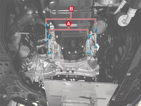
Install the IVT lower bolts (A, B).

Tightening torque :
(A) 42.2 - 48.1 N·m (4.3 - 4.9 kgf·m, 31.1 - 35.4 lb·ft)
(B) 42.2 - 53.9 N·m (4.3 - 5.5 kgf·m, 31.1 - 39.8 lb·ft)

Intelligent Variable Transmission (IVT) System — Intelligent Variable Transmission (IVT) / Installation illustration

5.
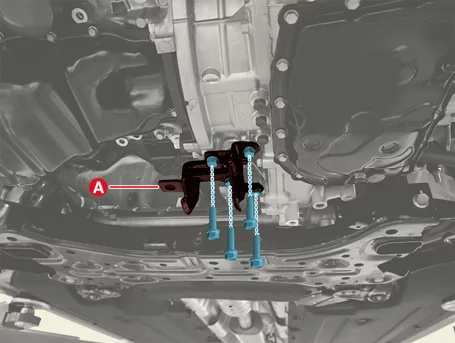
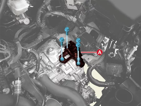
Install the roll rod support bracket (A).

Tightening torque :
49.0 - 68.6 N·m (5.0 - 7.0 kgf·m, 36.2 - 50.6 lb·ft)

Intelligent Variable Transmission (IVT) System — Intelligent Variable Transmission (IVT) / Installation illustration

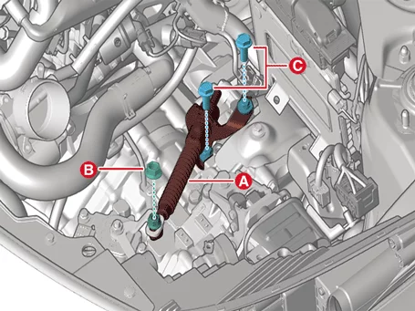
6.
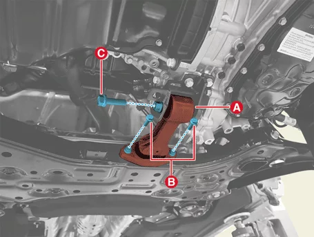
Install the roll rod bracket (A) by tightening the bolts (B, C).

Tightening torque :
(B) 49.0 - 63.7 N·m (5.0 - 6.5 kgf·m, 36.2 - 47.0 lb·ft)
(C) 107.9 - 127.5 N·m (11.0 - 13.0 kgf·m, 79.6 - 94.0 lb·ft)

Intelligent Variable Transmission (IVT) System — Intelligent Variable Transmission (IVT) / Installation illustration

7.
Install the transfer assembly. [4WD type]
(Refer to All Wheel Drive (AWD) System - "Front Wheel Transfer Assembly")
8.
Install the front driveshaft.
(Refer to Driveshaft and Axle - "Front Driveshaft")
9.
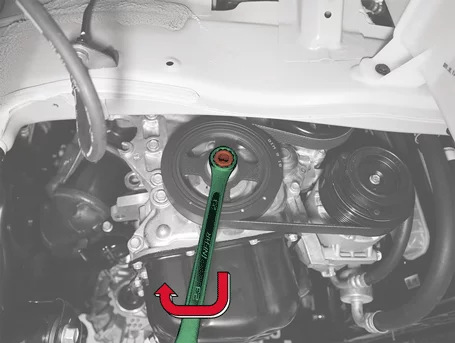
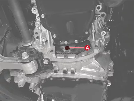
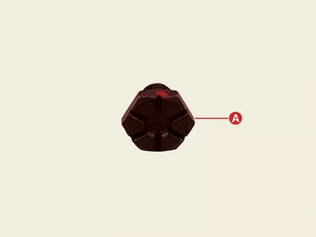
Install the torque converter bolts (A) after rotating the crankshaft in clockwise direction.

Tightening torque :
45.1 - 52.0 N·m (4.6 - 5.3 kgf·m, 33.3 - 38.3 lb·ft)

Intelligent Variable Transmission (IVT) System — Intelligent Variable Transmission (IVT) / Installation illustration

Intelligent Variable Transmission (IVT) System — Intelligent Variable Transmission (IVT) / Installation illustration

Note    
•
Lubricate the threads before tightening the torque converter bolts (A).

Intelligent Variable Transmission (IVT) System — Intelligent Variable Transmission (IVT) / Installation illustration

•
Pre-tighten the all torque converter mounting bolts (4pcs), then tighten to the specified torque securely
10.
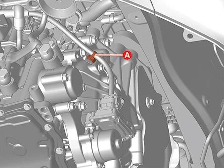
Install the wiring fixing clip (A).

Intelligent Variable Transmission (IVT) System — Intelligent Variable Transmission (IVT) / Installation illustration

11.
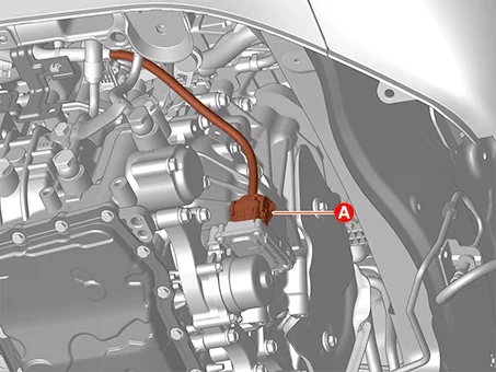
Connect the EOP connector (A).

Intelligent Variable Transmission (IVT) System — Intelligent Variable Transmission (IVT) / Installation illustration

12.
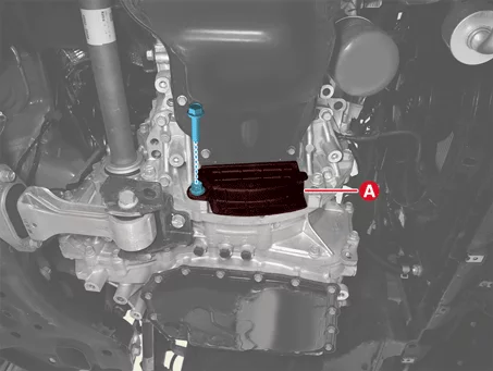
Install the cover (A).

Tightening torque :
42.2 - 48.1 N·m (4.3 - 4.9 kgf·m, 31.1 - 35.4 lb·ft)

Intelligent Variable Transmission (IVT) System — Intelligent Variable Transmission (IVT) / Installation illustration

13.
Install the wiring bracket (A).

Tightening torque :
9.8 - 11.8 N·m (1.0 - 1.2 kgf·m, 7.2 - 8.7 lb·ft)

Intelligent Variable Transmission (IVT) System — Intelligent Variable Transmission (IVT) / Installation illustration

14.
Support the IVT safely on a jack.

Intelligent Variable Transmission (IVT) System — Intelligent Variable Transmission (IVT) / Installation illustration

15.
Install the IVT support bracket (A).

Tightening torque :
58.8 - 78.5 N·m (6.0 - 8.0 kgf·m, 43.4 - 57.9 lb·ft)

Intelligent Variable Transmission (IVT) System — Intelligent Variable Transmission (IVT) / Installation illustration

16.
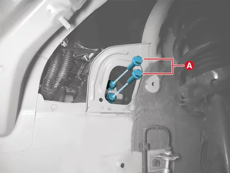
Install the IVT mounting bracket bolts (A).

Tightening torque :
98.1 - 117.7 N·m (10.0 - 12.0 kgf·m, 72.3 - 86.8 lb·ft)

Intelligent Variable Transmission (IVT) System — Intelligent Variable Transmission (IVT) / Installation illustration

Note    
When tightening bolts, first tighten the lower bolt and then the upper bolt.
17.
Install the left front wheel guard.
(Refer to Body - "Front Wheel Guard")
18.
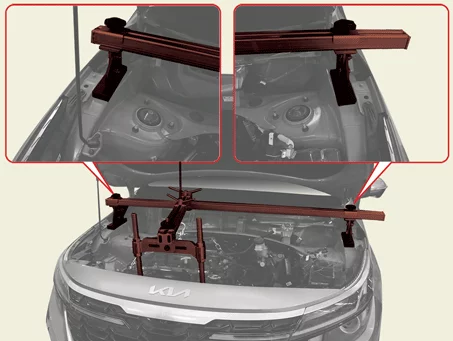
Remove the engine support.

Intelligent Variable Transmission (IVT) System — Intelligent Variable Transmission (IVT) / Installation illustration

19.
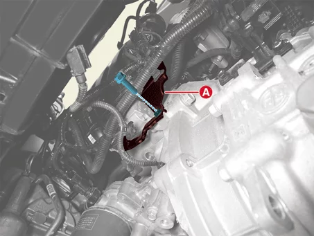
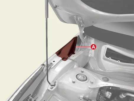
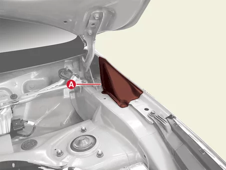
Install the cover (A).

Intelligent Variable Transmission (IVT) System — Intelligent Variable Transmission (IVT) / Installation illustration

Intelligent Variable Transmission (IVT) System — Intelligent Variable Transmission (IVT) / Installation illustration

20.
Install the cowl top cover.
(Refer to Body - "Cowl Top Cover")
21.
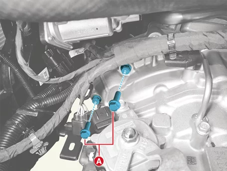
Install the starter bolts (A).

Tightening torque :
49.0 - 63.7 N·m (5.0 - 6.5 kgf·m, 36.2 - 47.0 lb·ft)

Intelligent Variable Transmission (IVT) System — Intelligent Variable Transmission (IVT) / Installation illustration

22.
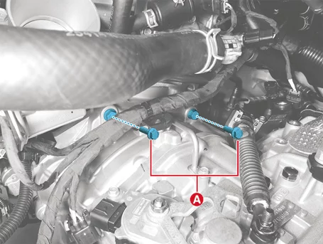
Install the IVT upper bolts (A).

Tightening torque :
42.2 - 53.9 N·m (4.3 - 5.5 kgf·m, 31.1 - 39.8 lb·ft)

Intelligent Variable Transmission (IVT) System — Intelligent Variable Transmission (IVT) / Installation illustration

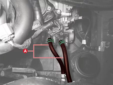
23.
Install the IVTF cooler hoses (A).

Intelligent Variable Transmission (IVT) System — Intelligent Variable Transmission (IVT) / Installation illustration

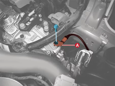
24.
Install the ground cable (A).

Tightening torque :
26.5 - 32.4 N·m (2.7 - 3.3 kgf·m, 19.5 - 23.9 lb·ft)

Intelligent Variable Transmission (IVT) System — Intelligent Variable Transmission (IVT) / Installation illustration

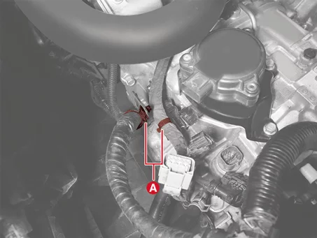
25.
Install the wiring fixing clips (A).

Intelligent Variable Transmission (IVT) System — Intelligent Variable Transmission (IVT) / Installation illustration

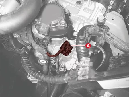
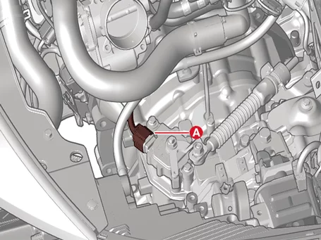
26.
Connect the main connector (A).

Intelligent Variable Transmission (IVT) System — Intelligent Variable Transmission (IVT) / Installation illustration

27.
Tighten the bolts (C) and nut (B) after installing the shift cable (A).

Tightening torque :
(B) 9.8 - 13.7 N·m (1.0 - 1.4 kgf·m, 7.2 - 10.1 lb·ft)
(C) 14.7 - 21.6 N·m (1.5 - 2.2 kgf·m, 10.8 - 15.9 lb·ft)

Intelligent Variable Transmission (IVT) System — Intelligent Variable Transmission (IVT) / Installation illustration

28.
Connect the position switch connector (A).

Intelligent Variable Transmission (IVT) System — Intelligent Variable Transmission (IVT) / Installation illustration

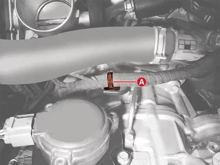
29.
Install the wiring fixing clip (A).

Intelligent Variable Transmission (IVT) System — Intelligent Variable Transmission (IVT) / Installation illustration

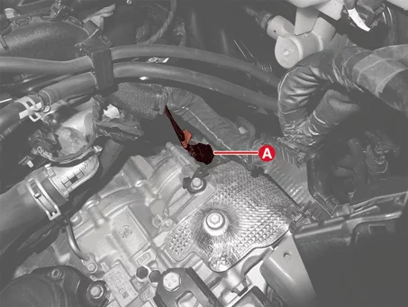
30.
Connect the driven pulley speed sensor connector (A).

Intelligent Variable Transmission (IVT) System — Intelligent Variable Transmission (IVT) / Installation illustration

31.
Install the battery and battery tray.
(Refer to Engine Electrical System - "Battery")
32.
Install the air cleaner assembly.
(Refer to Engine Mechanical System - "Air Cleaner")
33.
Install the engine room under cover.
(Refer to Engine Mechanical System - "Engine Room Under Cover")
34.
Perform the following tasks depending on whether the IVT is exchanged.
When reinstalling the IVT
(1)
If IVTF leakage occurs during IVT removal, replenish the IVTF, and check the level.
(Refer to Hydraulic System - "Fluid")
(2)
Clear the diagnostic trouble codes (DTC) using the KDS.
Note    
DTC cannot be deleted by disconnecting the battery terminals.
When installing a new IVT
(1)
Clear the diagnostic trouble codes (DTC) using the KDS.
Note    
DTC cannot be deleted by disconnecting the battery terminals.
(2)
Perform the resetting IVT transmission adaptive values using the KDS.
(S/W Management → Intelligent Variable Transmission → Resetting Auto T/A Values)
Information    
Refer to the KDS screen for operating conditions and details.
(3)
Perform the oil pressure characteristics input procedure using the KDS.
(S/W Management → Intelligent Variable Transmission → Oil-pressure Characteristics Input)
Information    
Refer to the KDS screen for operating conditions and details.
(4)
Perform TCM learning procedure.
(Refer to IVT Control System - "Adjustment ")

Other information:

Kia Seltos SP2 (2021-2026) Service Manual: Closing the fuel filler door

To install the fuel cap on the Kia Seltos, turn it clockwise until it clicks one time. This click indicates that the cap is securely tightened and properly sealed. Close the fuel filler door and press it lightly to make sure it is fully closed and flush with the body of the vehicle. WARNING Refueling Always remove the fuel cap carefully and slowly.

Kia Seltos SP2 (2021-2026) Service Manual: Emergency towing

If a professional towing service is not available during an emergency, your Kia Seltos may be temporarily towed using a suitable cable, chain, or towing strap attached only to the emergency towing hook located under the front or rear of the vehicle. Front Rear If towing is necessary, it is always best to have the Kia Seltos handled by an authorized Kia dealer or a professional commercial tow-truck service.