
Kia Seltos SP2 (2021-2026) Service Manual / Intelligent Variable Transmission (IVT) System / Intelligent Variable Transmission (IVT)
Kia Seltos: Intelligent Variable Transmission (IVT) System / Intelligent Variable Transmission (IVT)
Contents:
Components and Components Location
| Component |
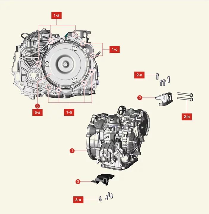
| 1. Intelligent Variable Transmission (IVT) 1-a. 42.2 - 53.9 N·m (4.3 - 5.5 kgf·m, 31.1 - 39.8 lb·ft) 1-b. 42.2 - 48.1 N·m (4.3 - 4.9 kgf·m, 31.1 - 35.4 lb·ft) 1-c. 49.0 - 63.7 N·m (5.0 - 6.5 kgf·m, 36.2 - 47.0 lb·ft) 2. IVT Support Bracket 2-a. 58.8 - 78.5 N·m (6.0 - 8.0 kgf·m, 43.4 - 57.9 lb·ft) 2-b. 98.1 - 117.7 N·m (10.0 - 12.0 kgf·m, 72.3 - 86.8 lb·ft) |
3. Roll Rod Support Bracket 3-a. 49.0 - 68.6 N·m (5.0 - 7.0 kgf·m, 36.2 - 50.6 lb·ft) 4. Torque Converter Assembly 4-a. 45.1 - 52.0 N·m (4.6 - 5.3 kgf·m, 33.3 - 38.3 lb·ft) |
Description and Operation
| Description |
IVT, which stands for Intelligent Variable Transmission, is an automatic transmission that continuously varies
gear ratios within a given shift range.
It uses the engine's high efficiency area to provide more power and better fuel economy.
| Operation |
IVT consists of a chain belt and two cone-shaped pulleys that transmit power.
It shift gears by changing the contact radius of the pulleys with hydraulic pressure according to driving
conditons.
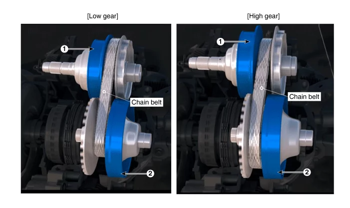
| 1. Driven Pulley (Output) |
2. Drive Pulley (Input) |
Removal
| Special Service Tool |
|
Tool Name / Number |
Illustration |
Description |
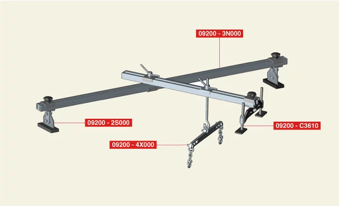
| Engine support fixture (bar) 09200 - 3N000 |
|
Used for holding engine assembly when removing / installing IVT transmission ※Refer to the engine support fixture assembly drawing below |
| Engine support fixture (supporter) 09200 - 2S000 09200 - 2S200 |
|
Used for holding engine assembly when removing / installing IVT
transmission (09200- 2S100 is unnecessary) ※Refer to the engine support fixture assembly drawing below |
|
Engine support fixture (front supporter) 09200 - C3610 |
|
Used for holding engine assembly when removing / installing IVT transmission ※Refer to the engine support fixture assembly drawing below |
| Engine support fixture (adapter) 09200 - 4X000 |
|
Used for holding engine assembly when removing / installing IVT transmission ※Refer to the engine support fixture assembly drawing below |
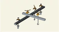
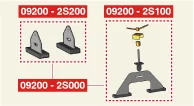
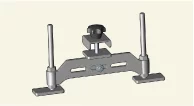
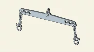
※ Engine support fixture assembly drawing
| Removal |
| 1. |
Remove the air cleaner assembly.
(Refer to Engine Mechanical System - "Air Cleaner")
|
| 2. |
Remove the battery and battery tray.
(Refer to Engine Electrical System - "Battery")
|
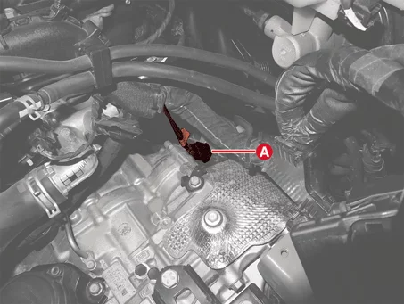
| 3. |
Disconnect the driven pulley speed sensor connector (A).
|
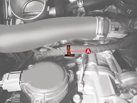
| 4. |
Separate the wiring fixing clip (A).
|
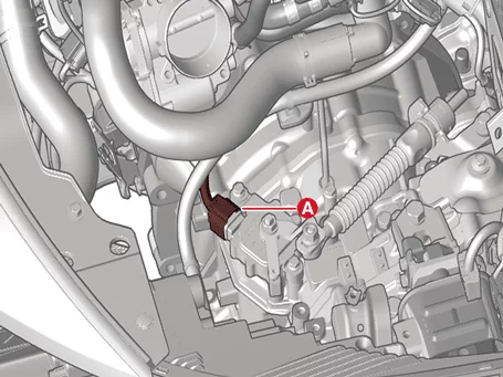
| 5. |
Disconnect the position switch connector (A).
|
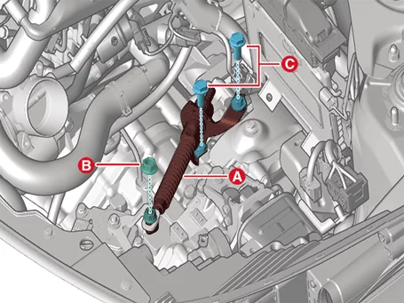
| 6. |
Remove the shift cable (A) after removing the bolts (C) and nut (B).
|
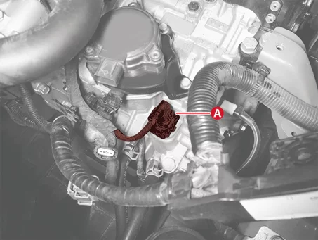
| 7. |
Disconnect the main connector (A).
|
| 8. |
Separate the wiring fixing clips (A).
|
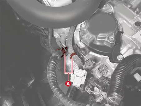
| 9. |
Remove the ground cable (A) by removing the bolt.
|
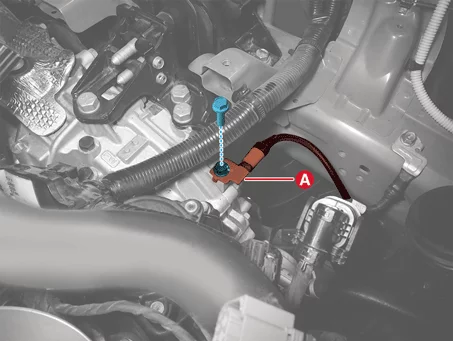
| 10. |
Separate the IVTF cooler hoses (A) after releasing the clamp.
|
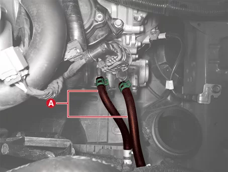
| 11. |
Remove the IVT upper bolts (A).
|
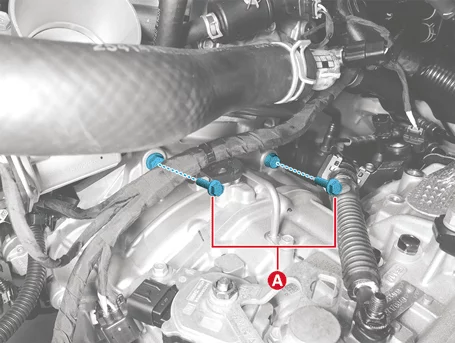
| 12. |
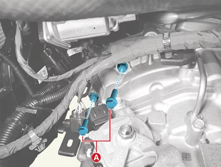
Remove the starter bolts (A).
|
| 13. |
Remove the cowl top cover.
(Refer to Body - "Cowl Top Cover")
|
| 14. |
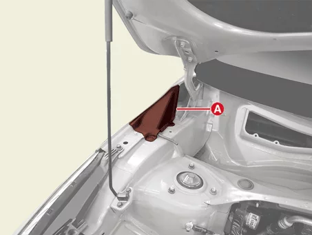
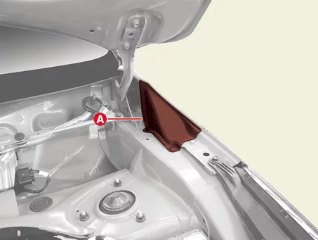
Remove the cover (A).
|
| 15. |
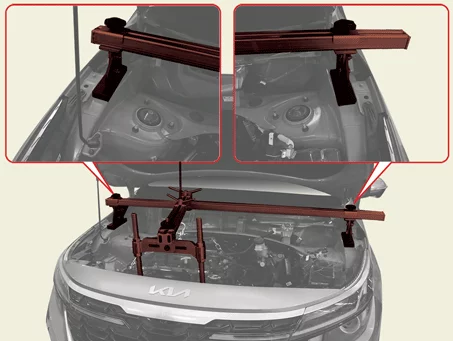
Assemble the engine support fixture in the engine room.
(Refer to Special Service Tools - "Engine support fixture assembly
drawing")
|
| 16. |
Remove the engine room under cover.
(Refer to Engine Mechanical System - "Engine Room Under Cover")
|
| 17. |
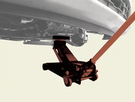
Support the IVT safely on a jack.
|
| 18. |
Remove the left front wheel guard.
(Refer to Body - "Front Wheel Guard")
|
| 19. |
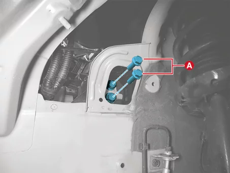
Remove the IVT mounting bracket bolts (A).
|
| 20. |
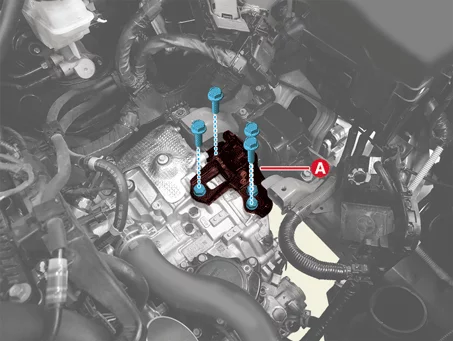
Remove the IVT support bracket (A) after removing the bolts.
|
| 21. |
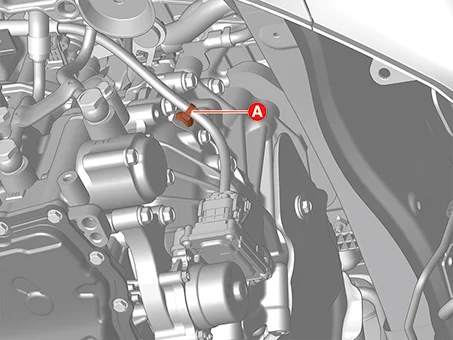
Separate the wiring fixing clip (A).
|
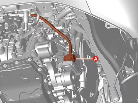
| 22. |
Disconnect the EOP connector (A).
|
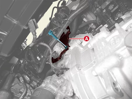
| 23. |
Remove the wiring bracket (A) after removing the bolt.
|
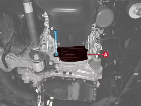
| 24. |
Remove the cover (A).
|
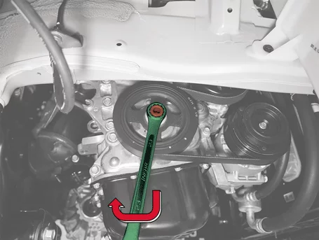
| 25. |
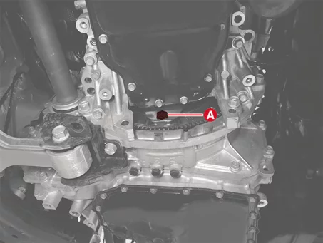
Remove the torque converter bolts (A) by rotating the crankshaft in clockwise direction.
|
| 26. |
Remove the front driveshaft.
(Refer to Driveshaft and Axle - "Front Driveshaft")
|
| 27. |
Remove the transfer assembly. [4WD type]
(Refer to All Wheel Drive (AWD) System - "Front Wheel Transfer
Assembly")
|
| 28. |
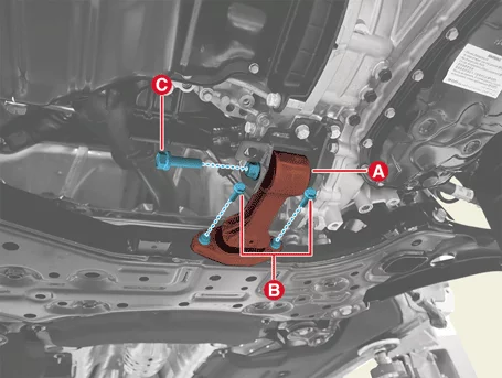
Remove the roll rod bracket (A) after removing the bolts (B, C).
|
| 29. |
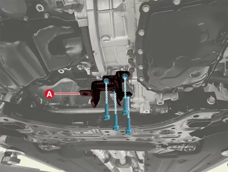
Remove the roll rod support bracket (A) by removing the bolts.
|
| 30. |
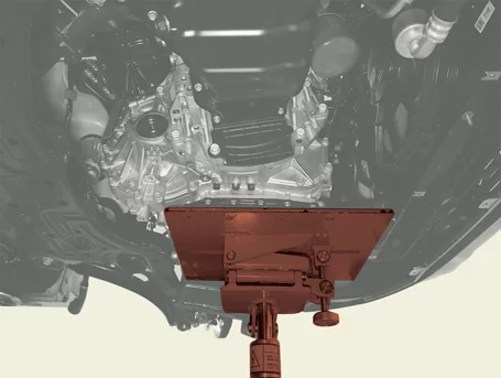
Support the IVT securely using a jack.
|
| 31. |
Remove the IVT lower bolts (A, B).
|
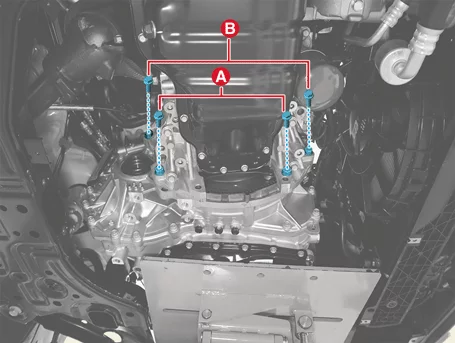
| 32. |
After separating the IVT from the engine, remove the IVT by lowering the jack slowly.
|

Installation ➤


Other information:
Forward Collision-Avoidance Assist (FCA) in the Kia Seltos is designed to help detect and monitor a vehicle ahead, or help detect a pedestrian or cyclist in the roadway. When the system determines that a collision risk is increasing, it may warn the driver with a warning message and audible alert, and may assist with emergency braking. Detecting sensor [1]: Front view camera Refer to the image above for the detailed location of the detecting sensor.Kia Seltos SP2 (2021-2026) Service Manual: Infotainment system vehicle settings
Vehicle Settings in the Kia Seltos infotainment system provide user options for adjusting door lock and unlock behavior, convenience features, driver assistance functions, display preferences, and other vehicle settings. Available menus may vary depending on trim level and equipment. WARNING Do not operate the Vehicle Settings menu while driving.