Contents:
Transmission Gear Oil Components and Components Location
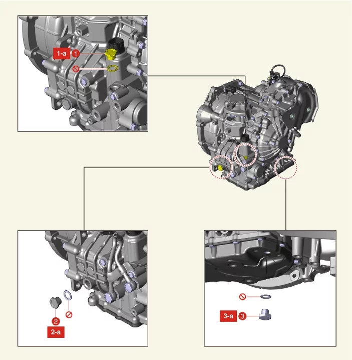
1. IVTF Filler Plug
1-a. 34.3 - 44.1 N·m (3.5 - 4.5
kgf·m, 25.3 - 32.5 lb·ft)
2. IVTF Level Plug
2-a. 34.3 - 44.1 N·m (3.5 - 4.5 kgf·m, 25.3 - 32.5
lb·ft)
|
3. IVTF Drain Plug
3-a. 34.3 - 39.2 N·m (3.5 - 4.0
kgf·m, 25.3 - 28.9 lb·ft)
|
Transmission Gear Oil Inspection
| Inspect the Intelligent Variable Transmission Fluid (IVTF) level
|
|
When checking the IVTF level, be careful not to allow foreign substance (like dust) to enter through the
filler hole.
|
| 1. |
Remove the air cleaner assembly.
(Refer to Engine Mechanical System - "Air Cleaner")
|
| 2. |
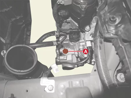
Remove the IVTF filler plug (A).
|
| 3. |
Start the engine to warm up the IVTF.
|
Do not step on the brake and accelerator simultaneously to warm up the IVTF.
|
|
| 4. |
Check by using KDS that the temperature of the IVTF is between 45 - 55°C (113 - 131°F).
|
| 5. |
Move the shift lever slowly from "P" to "D", then back to "P". Repeat this sequence two times and then
move the shift lever to "P" range.
|
Pause in each range for more than 2 seconds.
|
|
| 6. |
Remove the engine room under cover.
(Refer to Engine Mechanical System - "Engine Room Under Cover")
|
| 7. |
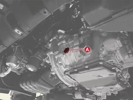
Lift the vehicle and remove the IVTF level plug (A).
|
When removing the IVTF level plug, keep the vehicle on a level ground.
|
|
| 8. |
Check the IVTF level.
Normal : 0.15 - 0.45 liters of IVTF flows out for 2
minutes
Excessive (abnormal) : Over 0.45 liters of IVTF flows out
for 2 minutes
Insufficient (abnormal) : Below 0.15 liters of IVTF flows
out for 2 minutes
|
|
If the IVTF level is too high or low, follow the instructions below.
|
•
|
Excessive : Drain until the IVTF flows out in a thin oil stream.
|
|
•
|
Insufficient : Add until the IVTF flows out in a thin oil stream.
|
|
|
| 9. |
Install the IVTF level plug (A).
Tightening torque :
34.3 - 44.1 N·m (3.5 - 4.5 kgf·m, 25.3 - 32.5 lb·ft)
|
|
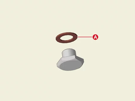
The existing IVTF level plug gasket (A) must be replaced with a new one (do not reuse).
|
|
| 10. |
Lower the vehicle and add the 0.3 liters (amount of oil drained during inspection) of SP-CVT1 through the
IVTF filler hole.
|
•
|
Be sure to use the genuine IVT Fluid (SP-CVT1)
|
|
•
|
When replacing with non-genuine IVT fluid, bad shift and vibration may occur, causing
damamge to the IVT.
|
|
•
|
Non-genuine IVT fluid includes after market IVT fluid indicated as interchangeable with
genuine Kia fluid.
|
|
|
| 11. |
Install the IVTF filler plug (A).
Tightening torque :
34.3 - 44.1 N·m (3.5 - 4.5 kgf·m, 25.3 - 32.5 lb·ft)
|
|
The existing IVTF filler plug gasket (A) must be replaced with a new one (do not reuse).
|
|
Transmission Gear Oil Replacement
| 1. |
Remove the engine room under cover.
(Refer to Engine Mechanical System - "Engine Room Under Cover")
|
| 2. |
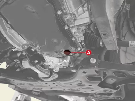
Remove the IVTF drain plug (A), allow the fluid to drain out and then reinstall the drain plug.
Tightening torque :
34.3 - 39.2 N·m (3.5 - 4.0 kgf·m, 25.3 - 28.9 lb·ft)
|
|
The existing IVTF drain plug gasket (A) must be replaced with a new one (do not reuse).
|
|
| 3. |
Remove the air cleaner assembly.
(Refer to Engine Mechanical System - "Air Cleaner")
|
| 4. |
Remove the IVTF filler plug (A).
|
| 5. |
Fill the IVT with 3.5 - 5.0 liters of ATF SP-CVT1 through the IVTF filler hole.
|
•
|
Be sure to use the genuine IVT Fluid (SP-CVT1)
|
|
•
|
When replacing with non-genuine IVT fluid, bad shift and vibration may occur, causing
damamge to the IVT.
|
|
•
|
Non-genuine IVT fluid includes after market IVT fluid indicated as interchangeable with
genuine Kia fluid.
|
|
|
| 6. |
Perform the IVTF level inspection procedure.
(Refer to Fluid - "Inspection")
|
Electric Oil Pump(EOP) Components and Components Location
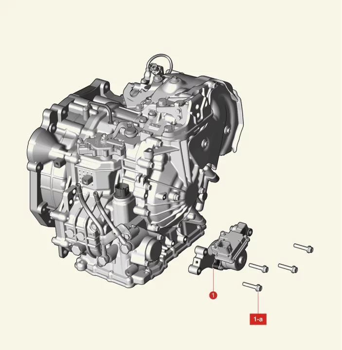
1. Electric Oil Pump (EOP)
|
1-a. 19.6 - 26.5 N·m (2.0 - 2.7 kgf·m, 14.5 - 19.5
lb·ft)
|
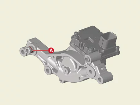
Electric Oil Pump(EOP) Removal and Installation
| 1. |
Disconnect the battery negative ( - ) terminal.
|
| 2. |
Remove the engine room under cover.
(Refer to Engine Mechanical System - "Engine Room Under Cover")
|
| 3. |
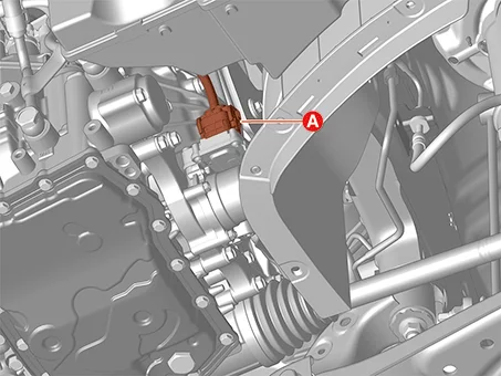
Disconnect the EOP connector (A).
|
| 4. |
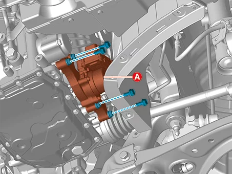
Remove the EOP (A) after removing the bolts.
Tightening torque :
19.6 - 26.5 N·m (2.0 - 2.7 kgf·m, 14.5 - 19.5 lb·ft)
|
|
| 1. |
Install in the reverse order of removal.
|
The existing O-ring (A) must be replaced with a new one (do not reuse).
|
|
| 2. |
Check the IVTF level after refilling the IVT with fluid.
(Refer to Hydraulic System - "Fluid")
|
| 3. |
Check for leakage of fluid from connection while the engine is starting and running.
|
Valve Body Components and Components Location
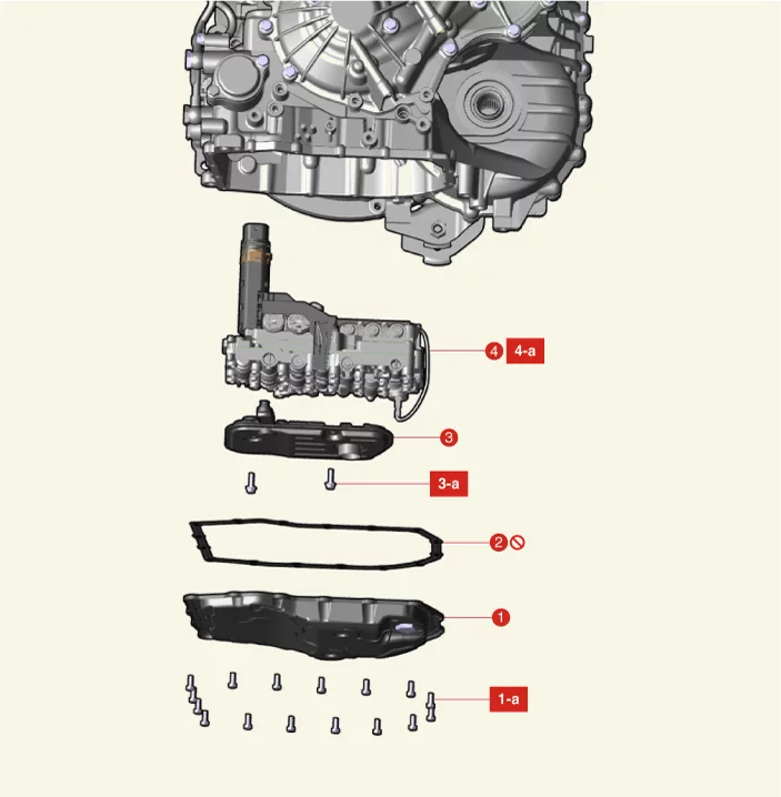
1. Valve Body Cover
1-a.
9.8 - 11.8 N·m (1.0 - 1.2 kgf·m, 7.2 - 8.7 lb·ft)
2. Valve Body Cover Gasket
|
3. IVTF Filter
3-a. 9.8 -
11.8 N·m (1.0 - 1.2 kgf·m, 7.2 - 8.7 lb·ft)
4. Valve Body
4-a. 9.8 - 11.8 N·m (1.0 - 1.2 kgf·m, 7.2 -
8.7 lb·ft)
|
Valve Body Description and Operation
There are four indirect solenoid valves and one direct solenoid valve mounted to the valve body in the oil fan.
Each indirect solenoid valve controls a driven pulley control valve (Secondary_VFS), drive pulley control valve
(Primary_VFS), line pressure control valve (Line_VFS), damper clutch control solenoid valve (Damper/C_VFS). Direct
solenoid valve controls drive/reverse clutch control solenoid valve (Clutch/Brake_VFS).
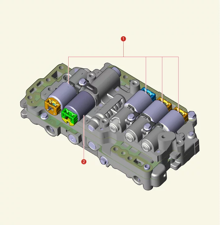
1. Indirect Control Solenoid Valve
|
2. Direct Control Solenoid Valve
|
Valve Body Removal
|
•
|
Maintain clean condition so that foreign substance does not get into the Intelligent Variable
Transmission (IVT).
|
|
•
|
Use a coated apron, latex gloves, and stainless tray to prevent foreign substance.
|
|
•
|
Intelligent Variable Transmission (IVT) is composed of delicate components. Be careful not to
cause any damage on the component when assembling and disassembling.
|
|
| 1. |
Disconnect the battery negative ( - ) terminal.
|
| 2. |
Remove the air cleaner assembly.
(Refer to Engine Mechanical System - "Air Cleaner")
|
| 3. |
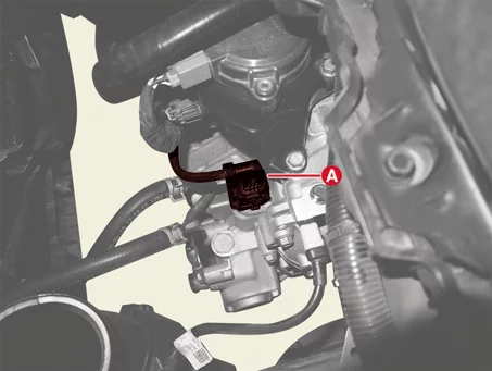
Disconnect the IVT main connector (A).
|
| 4. |
Remove the engine room under cover.
(Refer to Engine Mechanical System - "Engine Room Under Cover")
|
| 5. |
Remove the IVTF drain plug (A), allow the fluid to drain out and then reinstall the drain plug.
Tightening torque :
34.3 - 39.2 N·m (3.5 - 4.0 kgf·m, 25.3 - 28.9 lb·ft)
|
|
•
|
Intelligent variable transmission fluid (IVTF) can be reused. Collect it using a clean
10-liter beaker.
|
|
•
|
The existing IVTF drain plug gasket (A) must be replaced with a new one (do not reuse).
|
|
|
| 6. |
Remove the valve body cover (A) after removing the bolts.
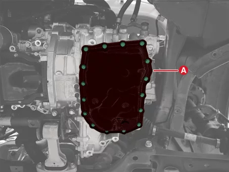
|
Be careful when removing the valve body cover because the remaining IVTF remains in the valve
body cover.
|
|
| 7. |
Remove the valve body cover gasket (A).
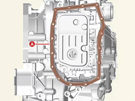
|
| 8. |
Remove the IVTF filter (A) after removing the bolts.
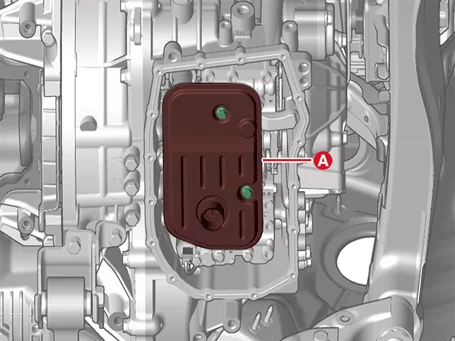
|
| 9. |
Remove the valve body assembly (A) after removing the bolts.
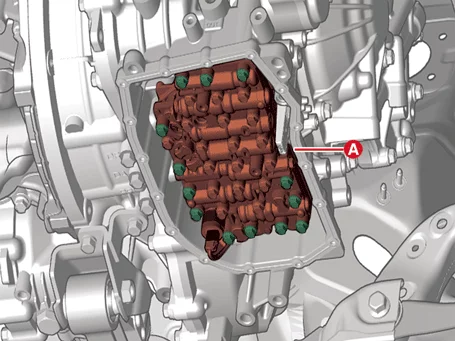
|
Be careful as residual IVTF may be drained when the valve body is removed.
|
|
Valve Body Installation
|
•
|
Maintain clean condition so that foreign substance does not get into the Intelligent Variable
Transmission (IVT).
|
|
•
|
Use a coated apron, latex gloves, and stainless tray to prevent foreign substance.
|
|
•
|
Intelligent Variable Transmission (IVT) is composed of delicate components. Be careful not to
cause any damage on the component when assembling and disassembling.
|
|
| 1. |
Install the valve body assembly (A).
Tightening torque :
9.8 - 11.8 N·m (1.0 - 1.2 kgf·m, 7.2 - 8.7 lb·ft)
|
|
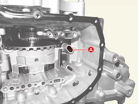
Check the installation condition of sealing (A) before installing the valve body.
|
|
| 2. |
Install the IVTF filter (A).
Tightening torque :
9.8 - 11.8 N·m (1.0 - 1.2 kgf·m, 7.2 - 8.7 lb·ft)
|
|
| 3. |
Install the valve body cover in the following order.
| (1)
|
Remove foreign substances from the surface of the IVT case and valve body cover.
|
| (2)
|
Install the valve body cover (A) and gasket (B), and temporarily tighten the bolts except
reference hole (C).
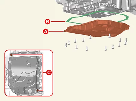
|
•
|
The existing valve body cover gasket must be replaced with a new one (do not
reuse).
|
|
•
|
Tighten the bolts by hand to adjust the position of the gasket.
|
|
|
| (3)
|
Visually check the reference hole (A) to align the valve body cover hole with the gasket hole.
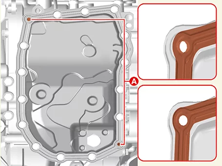
|
Tightening the bolts without aligning the valve body hole with the gasket hole may result
in any IVTF leaks.
|
|
| (4)
|
Tighten the remaining valve body cover mounting bolts except for the reference hole to the
tightening torque.
Tightening torque :
9.8 - 11.8 N·m (1.0 - 1.2 kgf·m, 7.2 - 8.7 lb·ft)
|
|
Tighten the bolts diagonally alternately so that pressure is evenly applied.
|
|
| (5)
|
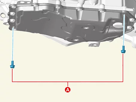
Check that the valve body cover hole and gasket hole are properly aligned through the reference
hole and tighten the bolt (A) to the reference hole.
Tightening torque :
9.8 - 11.8 N·m (1.0 - 1.2 kgf·m, 7.2 - 8.7 lb·ft)
|
|
| (6)
|
Check the valve body cover for damage (crack, deformation, etc.) and clean the IVTF around the
mounting area.
|
|
| 4. |
Check the IVTF level after refilling the intelligent variable transmission with fluid.
(Refer to Hydraulic System - "Fluid")
|
| 5. |
Connect the IVT main connector (A).
|
| 6. |
Install the air cleaner assembly.
(Refer to Engine Mechanical System - "Air Cleaner")
|
| 7. |
Check for leakage of IVT fluid from engine start.
|
| 8. |
Install the engine room under cover.
(Refer to Engine Mechanical System - "Engine Room Under Cover")
|
| 9. |
Perform the procedures below after in replacing the valve body assembly.
| (1)
|
Clear the diagnostic trouble codes (DTC) using the KDS.
(Disconnecting the battery negative terminal will not clear the DTCs. Clear DTCs using the KDS at
all times.)
|
| (2)
|
Perform the resetting IVT transmission adaptive values using the KDS.
(S/W Management → Intelligent Variable Transmission → Resetting Auto T/A Values)
|
Refer to the KDS screen for operating conditions and details.
|
|
| (3)
|
Perform the oil pressure characteristics input procedure using the KDS.
(S/W Management → Intelligent Variable Transmission → Oil-pressure Characteristics Input)
|
Refer to the KDS screen for operating conditions and details.
|
|
|
| 10. |
Perform the TCM adaptive values learning procedure.
(Refer to IVT Control System - "Adjustment ")
|
Damper Clutch Control Solenoid Valve (D/C_VFS) Specification
Item
|
Specification
|
Control type
|
Indirect control, N/L (Normal Low)
|
Control pressure [kPa (kgf/cm², psi)]
|
0 - 956.14 ± 14.71 (0 - 9.75 ± 0.15, 0 - 138.68 ± 2.13)
|
Current (mA)
|
0 - 1,100
|
Coil resistance (Ω)
|
5.0 - 5.6
|
Damper Clutch Control Solenoid Valve (D/C_VFS) Components and Components Location
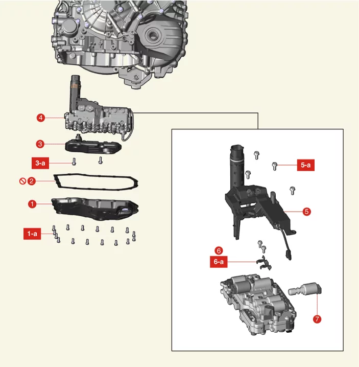
1. Valve Body Cover
1-a. 9.8 - 11.8 N·m (1.0 - 1.2
kgf·m, 7.2 - 8.7 lb·ft)
2. Valve Body Cover Gasket
3. IVTF Filter
3-a. 9.8 - 11.8 N·m (1.0 - 1.2
kgf·m, 7.2 - 8.7 lb·ft)
|
4. Valve Body Assembly
4-a. 9.8 - 11.8 N·m (1.0 -
1.2 kgf·m, 7.2 - 8.7 lb·ft)
5. E-Module
5-a. 9.8 - 11.8 N·m (1.0 - 1.2 kgf·m, 7.2 - 8.7 lb·ft)
6.
Support Bracket
6-a. 9.8 - 11.8 N·m (1.0 - 1.2 kgf·m, 7.2 - 8.7 lb·ft)
7. Damper Clutch Control Solenoid
Valve
|
Damper Clutch Control Solenoid Valve (D/C_VFS) On Vehicle Inspection
| 1. |
The Intelligent Variable Transmission system can be more quickly diagnosed for problems by using the
vehicle diagnostic system (KDS). (Refer to "DTC guide")
| (1)
|
Self diagnosis : Inspection and display fault code (DTC)
|
| (2)
|
Sensor data : Checking the system input/output data state
|
| (3)
|
Forced operation : Check the system operating condition
|
| (4)
|
Additional function : Controlling other features including system option setting and zero point
adjustment
|
|
| 2. |
Disconnect the battery negative ( - ) terminal.
|
| 3. |
Remove the air cleaner assembly.
(Refer to Engine Mechanical System - "Air Cleaner")
|
| 4. |
Disconnect the main connector (A).
|
| 5. |
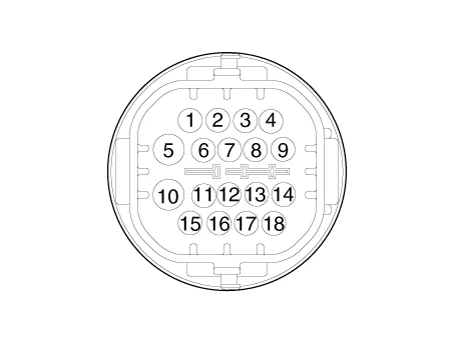
Measure the resistance between power terminal (10) and signal terminal (6).
Specification : 5.0 - 5.6 Ω
|
|
Damper Clutch Control Solenoid Valve (D/C_VFS) Removal and Installation
|
•
|
Maintain clean condition so that foreign substance does not get into the Intelligent Variable
Transmission (IVT).
|
|
•
|
Use a coated apron, latex gloves, and stainless tray to prevent foreign substance.
|
|
•
|
Intelligent Variable Transmission (IVT) is composed of delicate components. Be careful not to
cause any damage on the component when assembling and disassembling.
|
|
| 1. |
Remove the E-Module.
(Refer to IVT Control System - "E-Module")
|
| 2. |
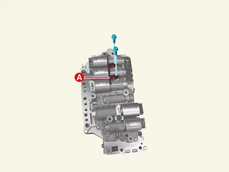
Remove the support bracket (A) after removing the bolts.
|
| 3. |
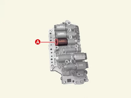
Remove the damper clutch control solenoid valve (A).
|
|
•
|
Maintain clean condition so that foreign substance does not get into the Intelligent Variable
Transmission (IVT).
|
|
•
|
Use a coated apron, latex gloves, and stainless tray to prevent foreign substance.
|
|
•
|
Intelligent Variable Transmission (IVT) is composed of delicate components. Be careful not to
cause any damage on the component when assembling and disassembling.
|
|
| 1. |
Install the damper clutch control solenoid valve (A).
|
| 2. |
Install the support bracket (A).
Tightening torque :
9.8 - 11.8 N·m (1.0 - 1.2 kgf·m, 7.2 - 8.7 lb·ft)
|
|
| 3. |
Install the E-Module.
(Refer to IVT Control System - "E-Module")
|
| 4. |
Perform the procedures below after in replacing the damper clutch control solenoid valve.
| (1)
|
Clear the diagnostic trouble codes (DTC) using the KDS.
(Disconnecting the battery negative terminal will not clear the DTCs.)
|
| (2)
|
Perform the resetting IVT transmission adaptive values using the KDS.
(S/W Management → Intelligent Variable Transmission → Resetting Auto T/A Values)
|
Refer to the KDS screen for operating conditions and details.
|
|
| (3)
|
Perform TCM learning procedure.
(Refer to IVT Control System - "Adjustment ")
|
|
Drive Pulley Control Solenoid Valve (Primary_VFS) Specification
Item
|
Specification
|
Control type
|
Indirect control, N/H (Normal High)
|
Control pressure [kPa (kgf/cm², psi)]
|
0 - 956.14 ± 14.71 (0 - 9.75 ± 0.15, 0 - 138.68 ± 2.13)
|
Current (mA)
|
0 - 1,100
|
Coil resistance (Ω)
|
5.0 - 5.6
|
Drive Pulley Control Solenoid Valve (Primary_VFS) Components and Components Location
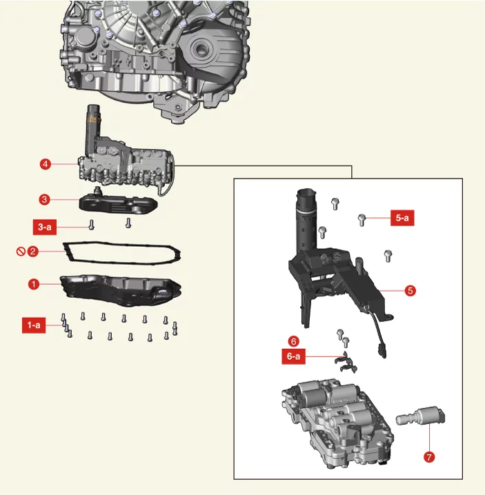
1. Valve Body Cover
1-a. 9.8 - 11.8 N·m (1.0 - 1.2
kgf·m, 7.2 - 8.7 lb·ft)
2. Valve Body Cover Gasket
3. IVTF Filter
3-a. 9.8 - 11.8 N·m (1.0 - 1.2
kgf·m, 7.2 - 8.7 lb·ft)
|
4. Valve Body Assembly
4-a. 9.8 - 11.8 N·m (1.0 -
1.2 kgf·m, 7.2 - 8.7 lb·ft)
5. E-Module
5-a. 9.8 - 11.8 N·m (1.0 - 1.2 kgf·m, 7.2 - 8.7 lb·ft)
6.
Support Bracket
6-a. 9.8 - 11.8 N·m (1.0 - 1.2 kgf·m, 7.2 - 8.7 lb·ft)
7. Drive Pulley Control Solenoid
Valve
|
Drive Pulley Control Solenoid Valve (Primary_VFS) On Vehicle Inspection
| 1. |
The Intelligent Variable Transmission system can be more quickly diagnosed for problems by using the
vehicle diagnostic system (KDS). (Refer to "DTC guide")
| (1)
|
Self diagnosis : Inspection and display fault code (DTC)
|
| (2)
|
Sensor data : Checking the system input/output data state
|
| (3)
|
Forced operation : Check the system operating condition
|
| (4)
|
Additional function : Controlling other features including system option setting and zero point
adjustment
|
|
| 2. |
Disconnect the battery negative ( - ) terminal.
|
| 3. |
Remove the air cleaner assembly.
(Refer to Engine Mechanical System - "Air Cleaner")
|
| 4. |
Disconnect the IVT main connector (A).
|
| 5. |
Measure the resistance between power terminal (10) and signal terminal (8).
Specification : 5.0 - 5.6 Ω
|
|
Drive Pulley Control Solenoid Valve (Primary_VFS) Removal and Installation
|
•
|
Maintain clean condition so that foreign substance does not get into the Intelligent Variable
Transmission (IVT).
|
|
•
|
Use a coated apron, latex gloves, and stainless tray to prevent foreign substance.
|
|
•
|
Intelligent Variable Transmission (IVT) is composed of delicate components. Be careful not to
cause any damage on the component when assembling and disassembling.
|
|
| 1. |
Remove the E-Module.
(Refer to IVT Control System - "E-Module")
|
| 2. |
Remove the support bracket (A) after removing the bolts.
|
| 3. |
Remove the drive pulley control solenoid valve (A).
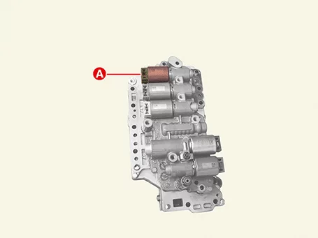
|
|
•
|
Maintain clean condition so that foreign substance does not get into the Intelligent Variable
Transmission (IVT).
|
|
•
|
Use a coated apron, latex gloves, and stainless tray to prevent foreign substance.
|
|
•
|
Intelligent Variable Transmission (IVT) is composed of delicate components. Be careful not to
cause any damage on the component when assembling and disassembling.
|
|
| 1. |
Install the drive pulley control solenoid valve (A).
|
| 2. |
Install the support bracket (A).
Tightening torque :
9.8 - 11.8 N·m (1.0 - 1.2 kgf·m, 7.2 - 8.7 lb·ft)
|
|
| 3. |
Install the E-Module.
(Refer to IVT Control System - "E-Module")
|
| 4. |
Perform the procedures below after replacing the drive pulley control solenoid valve with a new one.
| (1)
|
Clear the diagnostic trouble codes (DTC) using the KDS.
(Disconnecting the battery negative terminal will not clear the DTCs.)
|
| (2)
|
Perform the resetting IVT transmission adaptive values using the KDS.
(S/W Management → Intelligent Variable Transmission → Resetting Auto T/A Values)
|
Refer to the KDS screen for operating conditions and details.
|
|
| (3)
|
Perform TCM learning procedure.
(Refer to IVT Control System - "Adjustment ")
|
|
Driven Pulley Control Solenoid Valve (Secondary_VFS) Specification
Item
|
Specification
|
Control type
|
Indirect control, N/H (Normal High)
|
Control pressure [kPa (kgf/cm², psi)]
|
0 - 956.14 ± 14.71 (0 - 9.75 ± 0.15, 0 - 138.68 ± 2.13)
|
Current (mA)
|
0 - 1,100
|
Coil resistance (Ω)
|
5.0 - 5.6
|
Driven Pulley Control Solenoid Valve (Secondary_VFS) Components and Components Location
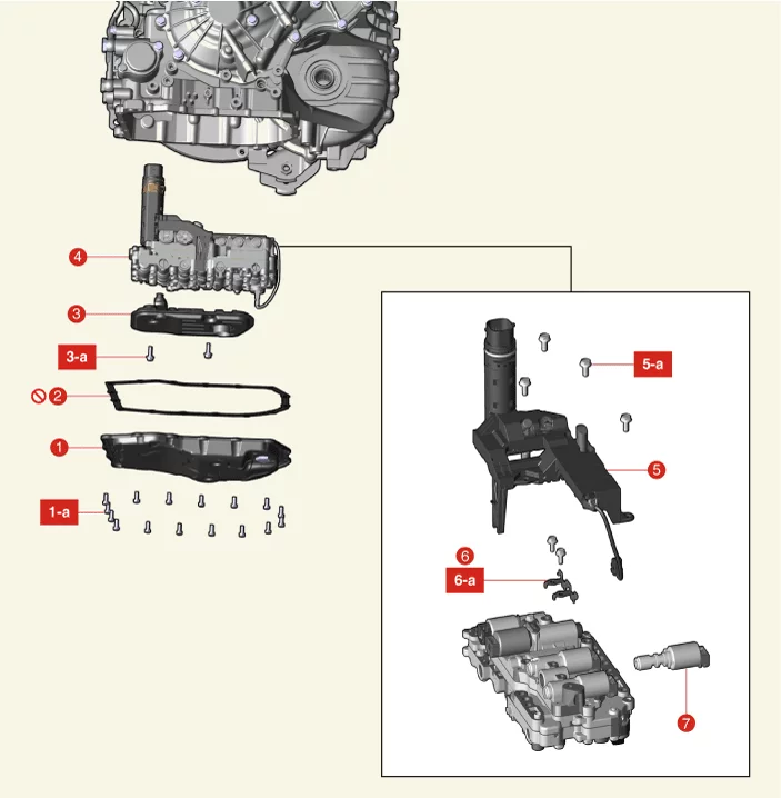
1. Valve Body Cover
1-a. 9.8 - 11.8 N·m (1.0 - 1.2
kgf·m, 7.2 - 8.7 lb·ft)
2. Valve Body Cover Gasket
3. IVTF Filter
3-a. 9.8 - 11.8 N·m (1.0 - 1.2
kgf·m, 7.2 - 8.7 lb·ft)
|
4. Valve Body Assembly
4-a. 9.8 - 11.8 N·m (1.0 -
1.2 kgf·m, 7.2 - 8.7 lb·ft)
5. E-Module
5-a. 9.8 - 11.8 N·m (1.0 - 1.2 kgf·m, 7.2 - 8.7 lb·ft)
6.
Support Bracket
6-a. 9.8 - 11.8 N·m (1.0 - 1.2 kgf·m, 7.2 - 8.7 lb·ft)
7. Driven Pulley Control Solenoid
Valve
|
Driven Pulley Control Solenoid Valve (Secondary_VFS) On Vehicle Inspection
| 1. |
The Intelligent Variable Transmission system can be more quickly diagnosed for problems by using the
vehicle diagnostic system (KDS). (Refer to "DTC guide")
| (1)
|
Self diagnosis : Inspection and display fault code (DTC)
|
| (2)
|
Sensor data : Checking the system input/output data state
|
| (3)
|
Forced operation : Check the system operating condition
|
| (4)
|
Additional function : Controlling other features including system option setting and zero point
adjustment
|
|
| 2. |
Disconnect the battery negative ( - ) terminal.
|
| 3. |
Remove the air cleaner assembly.
(Refer to Engine Mechanical System - "Air Cleaner")
|
| 4. |
Disconnect the IVT main connector (A).
|
| 5. |
Measure the resistance between power terminal (10) and signal terminal (7).
Specification : 5.0 - 5.6 Ω
|
|
Driven Pulley Control Solenoid Valve (Secondary_VFS) Removal and Installation
|
•
|
Maintain clean condition so that foreign substance does not get into the Intelligent Variable
Transmission (IVT).
|
|
•
|
Use a coated apron, latex gloves, and stainless tray to prevent foreign substance.
|
|
•
|
Intelligent Variable Transmission (IVT) is composed of delicate components. Be careful not to
cause any damage on the component when assembling and disassembling.
|
|
| 1. |
Remove the E-Module.
(Refer to IVT Control System - "E-Module")
|
| 2. |
Remove the support bracket (A) after removing the bolts.
|
| 3. |
Remove the driven pulley control solenoid valve (A).
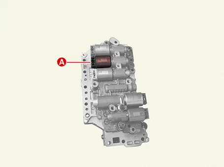
|
|
•
|
Maintain clean condition so that foreign substance does not get into the Intelligent Variable
Transmission (IVT).
|
|
•
|
Use a coated apron, latex gloves, and stainless tray to prevent foreign substance.
|
|
•
|
Intelligent Variable Transmission (IVT) is composed of delicate components. Be careful not to
cause any damage on the component when assembling and disassembling.
|
|
| 1. |
Install the driven pulley control solenoid valve (A).
|
| 2. |
Install the support bracket (A).
Tightening torque :
9.8 - 11.8 N·m (1.0 - 1.2 kgf·m, 7.2 - 8.7 lb·ft)
|
|
| 3. |
Install the E-Module.
(Refer to IVT Control System - "E-Module")
|
| 4. |
Perform the procedures below after in replacing the driven pulley control solenoid valve.
| (1)
|
Clear the diagnostic trouble codes (DTC) using the KDS.
(Disconnecting the battery negative terminal will not clear the DTCs.)
|
| (2)
|
Perform the resetting IVT transmission adaptive values using the KDS.
(S/W Management → Intelligent Variable Transmission → Resetting Auto T/A Values)
|
Refer to the KDS screen for operating conditions and details.
|
|
| (3)
|
Perform TCM learning procedure.
(Refer to IVT Control System - "Adjustment ")
|
|
Drive/Reverse Clutch Control Solenoid Valve (Clutch/Brake_VFS) Specification
Item
|
Specification
|
Control type
|
Direct control, N/H (Normal High)
|
Control pressure [kPa (kgf/cm², psi)]
|
0 - 1569.06 (0 - 16.00, 0 - 227.57)
|
Current (mA)
|
0 - 1,100
|
Coil resistance (Ω)
|
5.0 - 5.6
|
Drive/Reverse Clutch Control Solenoid Valve (Clutch/Brake_VFS) Components and Components Location
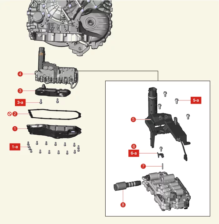
1. Valve Body Cover
1-a. 9.8 - 11.8 N·m (1.0 - 1.2
kgf·m, 7.2 - 8.7 lb·ft)
2. Valve Body Cover Gasket
3. IVTF Filter
3-a. 9.8 - 11.8 N·m (1.0 - 1.2
kgf·m, 7.2 - 8.7 lb·ft)
|
4. Valve Body Assembly
4-a. 9.8 - 11.8 N·m (1.0 -
1.2 kgf·m, 7.2 - 8.7 lb·ft)
5. E-Module
5-a. 9.8 - 11.8 N·m (1.0 - 1.2 kgf·m, 7.2 - 8.7 lb·ft)
6.
Support Bracket
6-a. 9.8 - 11.8 N·m (1.0 - 1.2 kgf·m, 7.2 - 8.7 lb·ft)
7. Roller
8. Drive/Reverse
Clutch Control Solenoid Valve
|
Drive/Reverse Clutch Control Solenoid Valve (Clutch/Brake_VFS) On Vehicle Inspection
| 1. |
The Intelligent Variable Transmission system can be more quickly diagnosed for problems by using the
vehicle diagnostic system (KDS). (Refer to "DTC guide")
| (1)
|
Self diagnosis : Inspection and display fault code (DTC)
|
| (2)
|
Sensor data : Checking the system input/output data state
|
| (3)
|
Forced operation : Check the system operating condition
|
| (4)
|
Additional function : Controlling other features including system option setting and zero point
adjustment
|
|
| 2. |
Disconnect the battery negative ( - ) terminal.
|
| 3. |
Remove the air cleaner assembly.
(Refer to Engine Mechanical System - "Air Cleaner")
|
| 4. |
Disconnect the IVT main connector (A).
|
| 5. |
Measure the resistance between power terminal (5) and signal terminal (11).
Specification : 5.0 - 5.6 Ω
|
|
Drive/Reverse Clutch Control Solenoid Valve (Clutch/Brake_VFS) Removal and Installation
|
•
|
Maintain clean condition so that foreign substance does not get into the Intelligent Variable
Transmission (IVT).
|
|
•
|
Use a coated apron, latex gloves, and stainless tray to prevent foreign substance.
|
|
•
|
Intelligent Variable Transmission (IVT) is composed of delicate components. Be careful not to
cause any damage on the component when assembling and disassembling.
|
|
| 1. |
Remove the E-Module.
(Refer to IVT Control System - "E-Module")
|
| 2. |
Remove the support bracket (A) after removing the bolts.
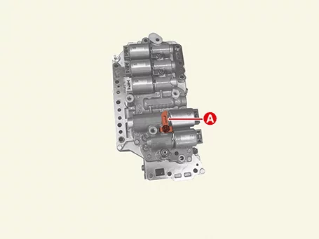
|
| 3. |
Remove the roller (A) using a magnet.
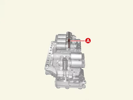
|
| 4. |
Remove the drive/reverse clutch control solenoid valve (A).
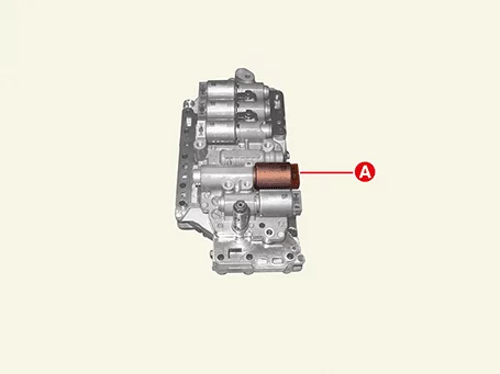
|
|
•
|
Maintain clean condition so that foreign substance does not get into the Intelligent Variable
Transmission (IVT).
|
|
•
|
Use a coated apron, latex gloves, and stainless tray to prevent foreign substance.
|
|
•
|
Intelligent Variable Transmission (IVT) is composed of delicate components. Be careful not to
cause any damage on the component when assembling and disassembling.
|
|
| 1. |
Install the drive/reverse clutch control solenoid valve (A).
|
•
|
Check the oil pressure characteristics value (A) at the first before installing the
solenoid valve.
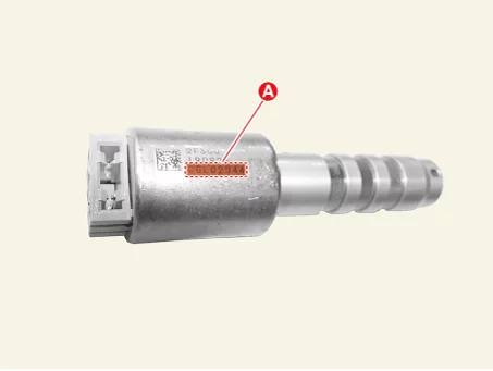
|
|
•
|
If incorrect hydraulic characteristics are entered, the shift shock may occur during TCM
learning, so note the engraved hydraulic values carefully.
|
|
|
| 2. |
Install the roller (A).
|
| 3. |
Install the support bracket (A).
Tightening torque :
9.8 - 11.8 N·m (1.0 - 1.2 kgf·m, 7.2 - 8.7 lb·ft)
|
|
| 4. |
Install the E-Module.
(Refer to IVT Control System - "E-Module")
|
| 5. |
Perform the procedures below after in replacing the drive/reverse clutch control solenoid valve.
| (1)
|
Clear the diagnostic trouble codes (DTC) using the KDS.
(Disconnecting the battery negative terminal will not clear the DTCs.)
|
| (2)
|
Perform the resetting IVT transmission adaptive values using the KDS.
(S/W Management → Intelligent Variable Transmission → Resetting Auto T/A Values)
|
Refer to the KDS screen for operating conditions and details.
|
|
| (3)
|
Perform the oil pressure characteristics input procedure using the KDS.
(S/W Management → Intelligent Variable Transmission → Oil-pressure Characteristics Input)
|
Refer to the KDS screen for operating conditions and details.
|
|
| (4)
|
Perform TCM learning procedure.
(Refer to IVT Control System - "Adjustment ")
|
|
Line Pressure Control Solenoid Valve (LINE_VFS) Specification
Item
|
Specification
|
Control type
|
Indirect control, N/H (Normal High)
|
Control pressure [kPa (kgf/cm², psi)]
|
0 - 956.14 ± 14.71 (0 - 9.75 ± 0.15, 0 - 138.68 ± 2.13)
|
Current (mA)
|
0 - 1,100
|
Coil resistance (Ω)
|
5.0 - 5.6
|
Line Pressure Control Solenoid Valve (LINE_VFS) Components and Components Location
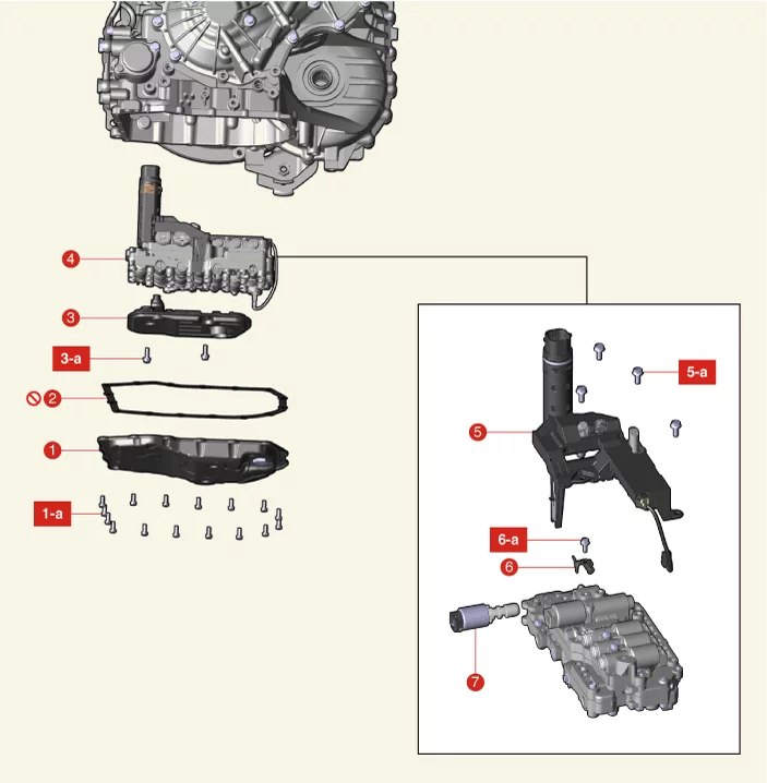
1. Valve Body Cover
1-a. 9.8 - 11.8 N·m (1.0 - 1.2
kgf·m, 7.2 - 8.7 lb·ft)
2. Valve Body Cover Gasket
3. IVTF Filter
3-a. 9.8 - 11.8 N·m (1.0 - 1.2
kgf·m, 7.2 - 8.7 lb·ft)
|
4. Valve Body Assembly
4-a. 9.8 - 11.8 N·m (1.0 -
1.2 kgf·m, 7.2 - 8.7 lb·ft)
5. E-Module
5-a. 9.8 - 11.8 N·m (1.0 - 1.2 kgf·m, 7.2 - 8.7 lb·ft)
6.
Support Bracket
6-a. 9.8 - 11.8 N·m (1.0 - 1.2 kgf·m, 7.2 - 8.7 lb·ft)
7. Line Pressure Control Solenoid
Valve
|
Line Pressure Control Solenoid Valve (LINE_VFS) On Vehicle Inspection
| 1. |
The Intelligent Variable Transmission system can be more quickly diagnosed for problems by using the
vehicle diagnostic system (KDS). (Refer to "DTC guide")
| (1)
|
Self diagnosis : Inspection and display fault code (DTC)
|
| (2)
|
Sensor data : Checking the system input/output data state
|
| (3)
|
Forced operation : Check the system operating condition
|
| (4)
|
Additional function : Controlling other features including system option setting and zero point
adjustment
|
|
| 2. |
Disconnect the battery negative ( - ) terminal.
|
| 3. |
Remove the air cleaner assembly.
(Refer to Engine Mechanical System - "Air Cleaner")
|
| 4. |
Disconnect the IVT main connector (A).
|
| 5. |
Measure the resistance between power terminal (5) and signal terminal (12).
Specification : 5.0 - 5.6 Ω
|
|
Line Pressure Control Solenoid Valve (LINE_VFS) Removal and Installation
|
•
|
Maintain clean condition so that foreign substance does not get into the Intelligent Variable
Transmission (IVT).
|
|
•
|
Use a coated apron, latex gloves, and stainless tray to prevent foreign substance.
|
|
•
|
Intelligent Variable Transmission (IVT) is composed of delicate components. Be careful not to
cause any damage on the component when assembling and disassembling.
|
|
| 1. |
Remove the E-Module.
(Refer to IVT Control System - "E-Module")
|
| 2. |
Remove the support bracket (A) after removing the bolts.
|
| 3. |
Remove the line pressure control solenoid valve (A).
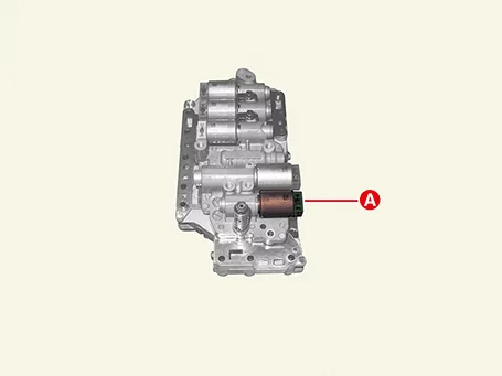
|
|
•
|
Maintain clean condition so that foreign substance does not get into the Intelligent Variable
Transmission (IVT).
|
|
•
|
Use a coated apron, latex gloves, and stainless tray to prevent foreign substance.
|
|
•
|
Intelligent Variable Transmission (IVT) is composed of delicate components. Be careful not to
cause any damage on the component when assembling and disassembling.
|
|
| 1. |
Install the line pressure control solenoid valve (A).
|
| 2. |
Install the support bracket (A).
Tightening torque :
9.8 - 11.8 N·m (1.0 - 1.2 kgf·m, 7.2 - 8.7 lb·ft)
|
|
| 3. |
Install the E-Module.
(Refer to IVT Control System - "E-Module")
|
| 4. |
Perform the procedures below after in replacing the line pressure control solenoid valve.
| (1)
|
Clear the diagnostic trouble codes (DTC) using the KDS.
(Disconnecting the battery negative terminal will not clear the DTCs.)
|
| (2)
|
Perform the resetting IVT transmission adaptive values using the KDS.
(S/W Management → Intelligent Variable Transmission → Resetting Auto T/A Values)
|
Refer to the KDS screen for operating conditions and details.
|
|
| (3)
|
Perform TCM learning procedure.
(Refer to IVT Control System - "Adjustment ")
|
|
Pressure Filter Removal and Installation
| 1. |
Remove the engine room under cover.
(Refer to Engine Mechanical System - "Engine Room Under Cover")
|
| 2. |
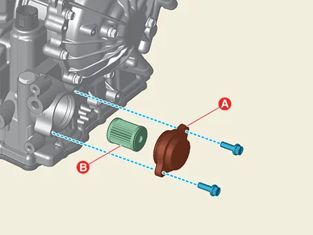
Remove the pressure filter cover (A) and pressure filter (B) after removing the bolts.
Tightening torque :
19.6 - 26.5 N·m (2.0 - 2.7 kgf·m, 14.5 - 19.5 lb·ft)
|
|
•
|
When removing the cover, the pressure filter is also removed.
|
|
•
|
When the cover is removed, a small amount of IVTF is discharged.
|
|
|
| 1. |
Install in the reverse order of removal.
|
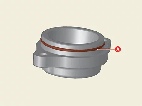
Before installing the pressure filter cover, check the O-ring (A) is installed properly.
|
|
| 2. |
Perform the IVTF level inspection procedure.
(Refer to Transmission Gear Oil - "Inspection")
|



