
Kia Seltos: Driveshaft and Axle / Driveshaft Assembly
Contents:
- Front Driveshaft Components and Components Location
- Front Driveshaft Removal and Installation
- Joint Assembly (Transaxle side) Components and Components Location
- Joint Assembly (Transaxle side) Removal
- Joint Assembly (Transaxle side) Inspection
- Joint Assembly (Transaxle side) Installation
- Joint Assembly (Wheel side) Components and Components Location
- Joint Assembly (Wheel side) Removal
- Joint Assembly (Wheel side) Inspection
- Joint Assembly (Wheel side) Installation
Front Driveshaft Components and Components Location
| Component |
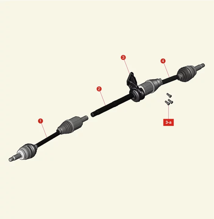
| 1. Front driveshaft [LH] 2. Innershaft |
3. Innershaft Bearing Bracket 3-a. 49.0 - 63.7 N·m (5.0 - 6.5 kgf·m, 36.2 - 47 lb·ft) 4. Front driveshaft [RH] |
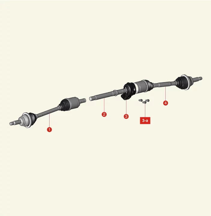
| 1. Front driveshaft [LH] 2. Innershaft |
3. Innershaft Bearing Bracket 3-a. 49.0 - 63.7 N·m (5.0 - 6.5 kgf·m, 36.2 - 47 lb·ft) 4. Front driveshaft [RH] |
Front Driveshaft Removal and Installation
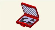
| Special Service Tool |
|
Tool Name / Number |
Illustration |
Description |
|
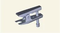
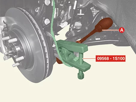
Ball joint puller 09568 - 1S100 |
|
Used for removal of tie rod end |
|
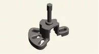
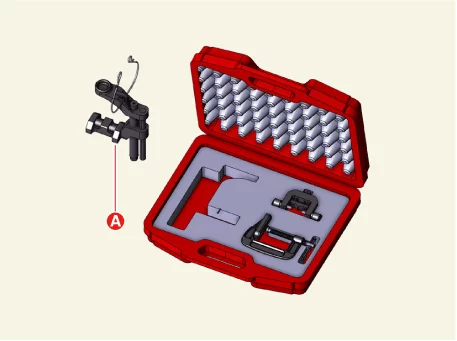
CV joint puller 09517 - 4E000 |
|
Used for removal of CV joint |
|
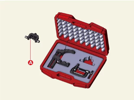
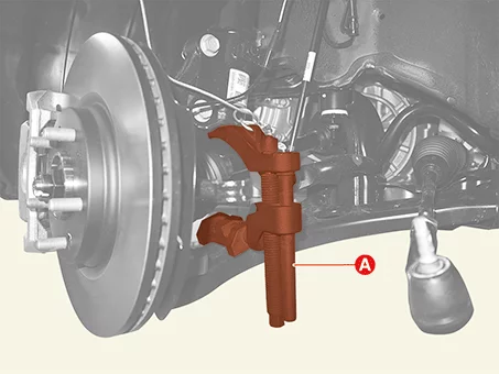
Lower arm ball joint remover 0K545 - A9100 |
|
Used for removal of front lower arm ball joint |
| Removal |
| Front Driveshaft |
| 1. |
Remove the front wheel and tires.
(Refer to Suspension System - "Wheel")
|
| 2. |
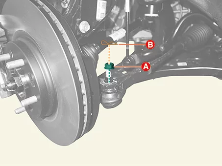
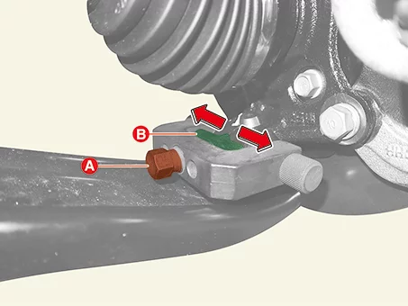
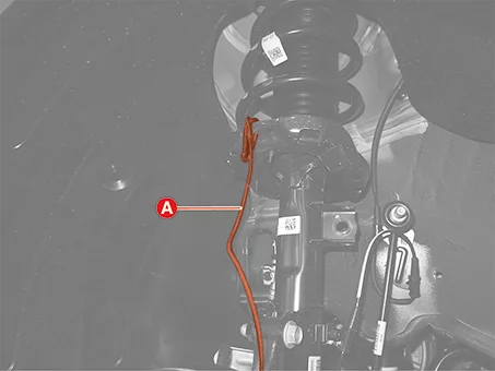
Separate the tie rod end ball joint from the front axle.
|

| 3. |
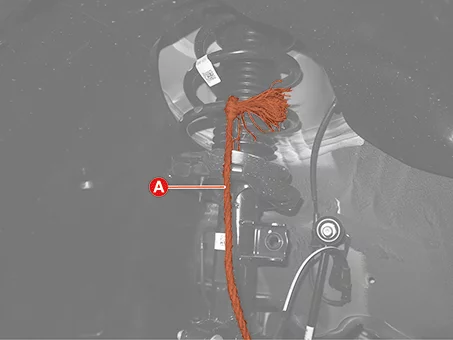
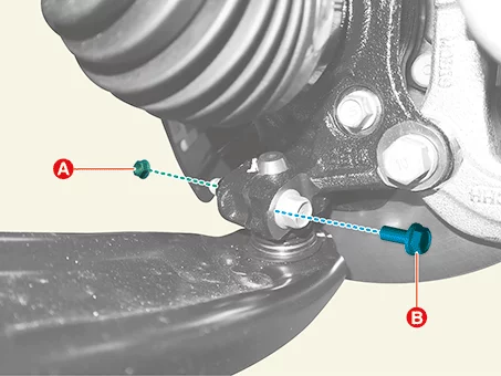
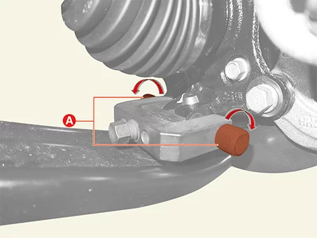
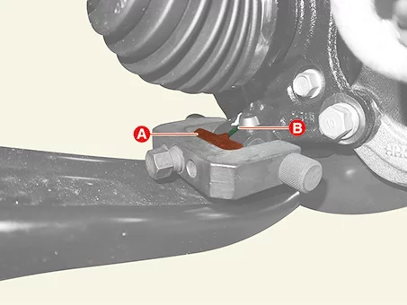
Separate the lower arm ball joint from the front axle.
|

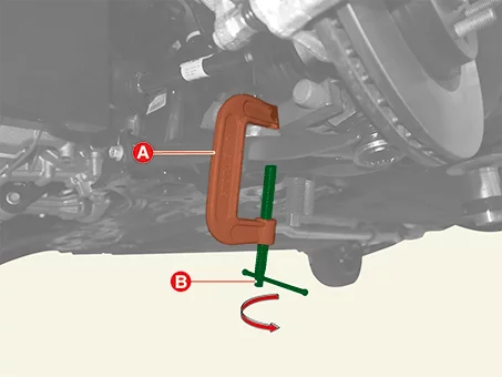
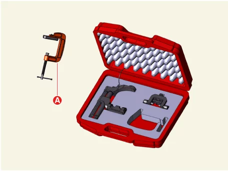
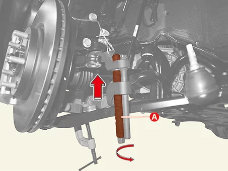
| 4. |
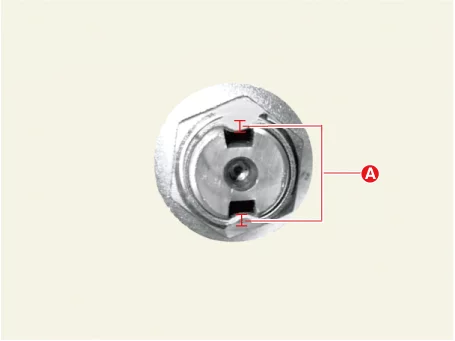
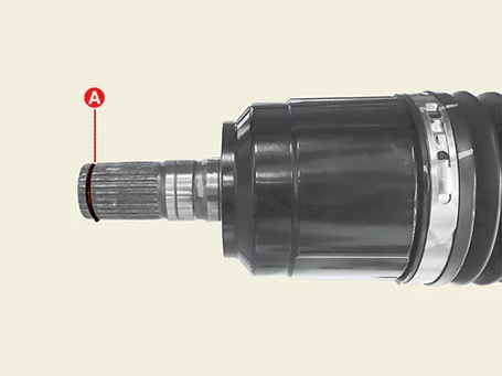
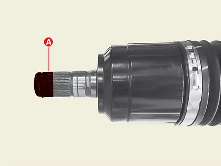
Unlock the driveshaft lock nut caulking (A), by hammering on a chisel or suitable tool.
|
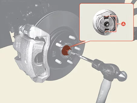
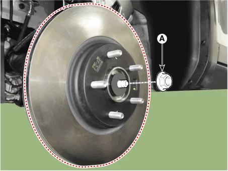
| 5. |
Remove the driveshaft lock nut (A).
|
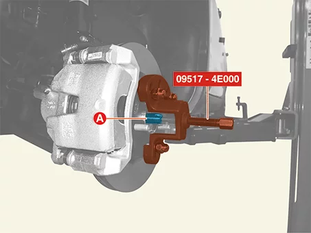
| 6. |
Separate the front driveshaft (A) from the front axle by using the SST (09517 - 4E000).
|
| 7. |
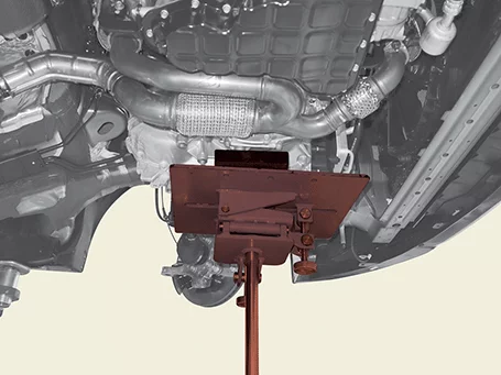
Remove the engine room under cover.
G 1.6 T-GDI GAMMA II (Refer to Engine Mechanical System - "Engine Room
Under Cover")
G 2.0 MPI NU (Refer to Engine Mechanical System - "Engine Room Under
Cover")
|
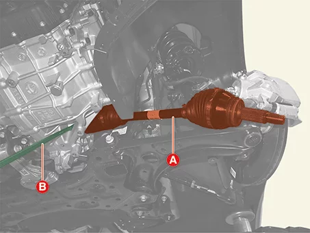
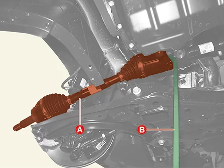
| 8. |
Remove the front driveshaft (A) using a tool such as the pry bar (B).
[LH]
[RH]
|
| 1. |
Remove the RH front driveshaft.
(Refer to Driveshaft Assembly - "Front Driveshaft")
|
| 2. |
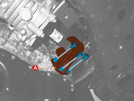
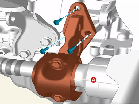
Separate the inner shaft bearing bracket (A) from the cylinder block after removing the bolts.
[G 1.6 T-GDI GAMMA II]
[G 2.0 MPI NU]
|
| 3. |
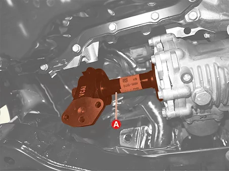
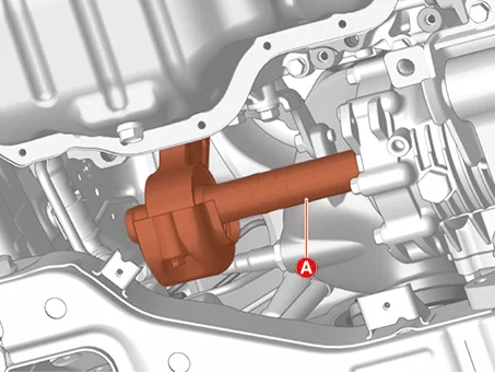
Remove the inner shaft and bearing bracket (A).
[G 1.6 T-GDI GAMMA II]
[G 2.0 MPI NU]
|
| Installation |
| 1. |
Install in reverse order of removal.
|
Joint Assembly (Transaxle side) Components and Components Location
| Component |
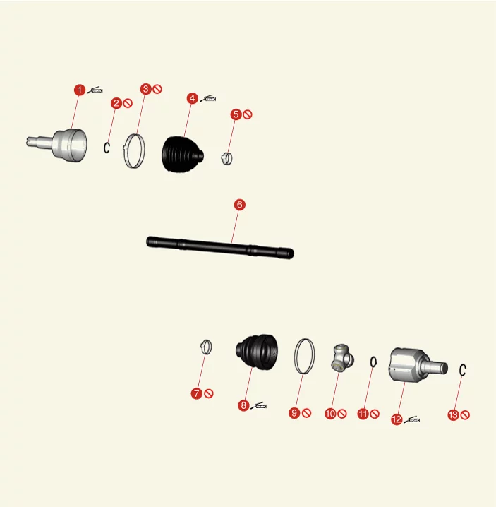
| 1. Wheel Side Joint Housing 2. Circlip (Wheel Side) 3. Large Diameter Boot Band (Wheel Side) 4. Boot (Wheel Side) 5. Small Diameter Boot Band (Wheel Side) 6. Shaft |
7. Small Diameter Boot Band (Transaxle Side) 8. Boot (Transaxle Side) 9. Large Diameter Boot Band (Transaxle Side) 10. Spider Assembly 11. Snap Ring 12. Transaxle Side Joint Housing 13. Circlip (Transaxle Side) |
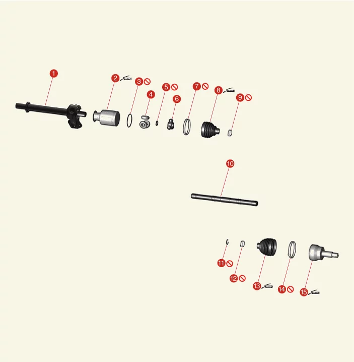
| 1. Inner Shaft Assembly 2. Transaxle Side Joint Housing 3. Stopper Ring 4. Spider Assembly Bearing 5. Snap Ring 6. Spider Assembly 7. Large Diameter Boot Band (Transaxle Side) 8. Boot |
9. Small Diameter Boot Band (Transaxle Side) 10. Shaft 11. Circlip (Wheel Side) 12. Small Diameter Boot Band (Wheel Side) 13. Boot 14. Large Diameter Boot Band (Wheel Side) 15. Wheel Side Joint Housing |
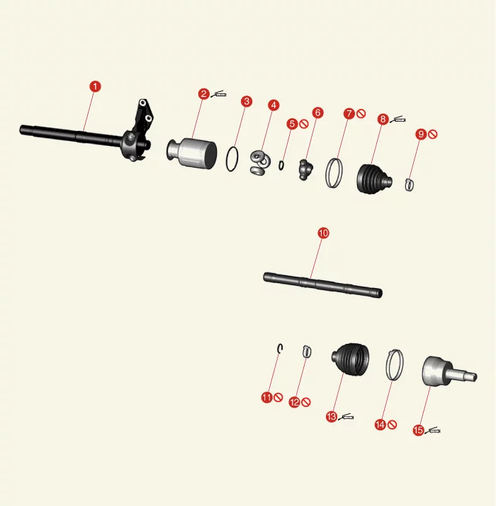
| 1. Inner Shaft Assembly 2. Transaxle Side Joint Housing 3. Stopper Ring 4. Spider Assembly Bearing 5. Snap Ring 6. Spider Assembly 7. Large Diameter Boot Band (Transaxle Side) 8. Boot |
9. Small Diameter Boot Band (Transaxle Side) 10. Shaft 11. Circlip (Wheel Side) 12. Small Diameter Boot Band (Wheel Side) 13. Boot 14. Large Diameter Boot Band (Wheel Side) 15. Wheel Side Joint Housing |
Joint Assembly (Transaxle side) Removal
| Special Service Tool |
|
Tool Name / Number |
Illustration |
Description |
|
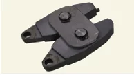
Band installer 0K495 - 2W000 |
|
Used for installing hook type boot band (low profile)(Sharing handle with 0K495 - C5000) |
| Removal |
|
| 1. |
Remove the front driveshaft.
(Refer to Driveshaft Assembly - "Front Driveshaft")
|
| 2. |
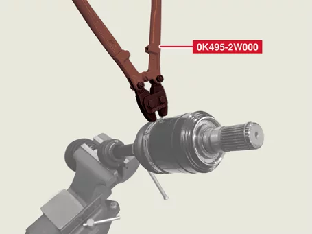
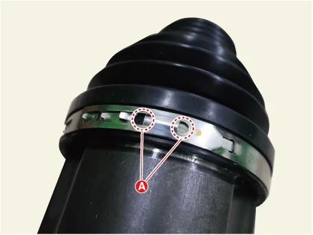
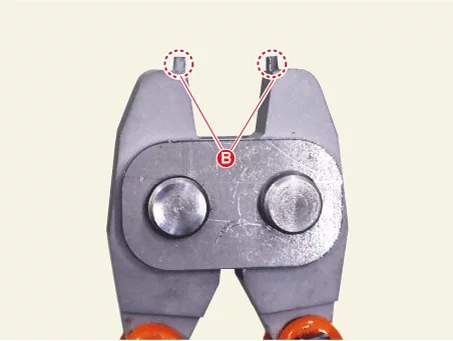
Remove the large diameter boot band using the SST (0K495 - 2W000).
|
| 3. |
Remove the transaxle side small diameter boot band (A) using the flat-head screwdriver.
|
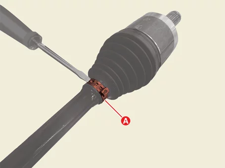
| 4. |
Separate the transaxle side joint boot (A) in the direction of the arrow, and then remove the joint
stopper ring (B) and joint housing (C).
|
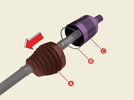
| 5. |
Remove the bearings (A) from the spider assembly.
|
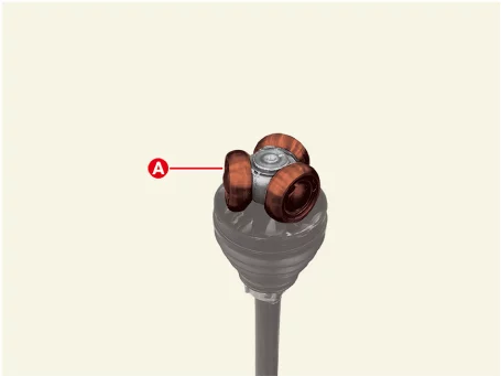
| 6. |
Remove the snap ring (A) using the snap ring pliers.
|
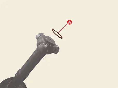
| 7. |
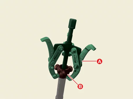
Remove the spider assembly (B) from the driveshaft using a puller (A).
|
| 8. |
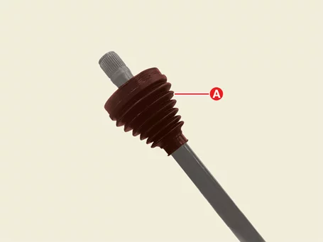
Remove transaxle side boot (A).
|
| 9. |
Clean the inside of the spider assembly and joint housing.
|
Joint Assembly (Transaxle side) Inspection
| Inspection |
| 1. |
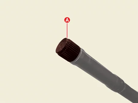
Check spline (A) for damage / wear / crack.
|
| 2. |
Check the boot for water or foreign objects.
|
| 3. |
Check joint assembly for damage / wear / crack and rust.
|
| 4. |
Replace any defective parts.
|
Joint Assembly (Transaxle side) Installation
| Special Service Tool |
|
Tool Name / Number |
Illustration |
Description |
|
Band installer 0K495 - C5000 |
|
Used for installing ear type boot band(Sharing handle with 0K495 - 2W000) |
|
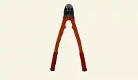
Band installer 0K495 - 2W000 |
|
Used for installing hook type boot band (low profile)(Sharing handle with 0K495 - C5000) |
| Installation |
|
| 1. |
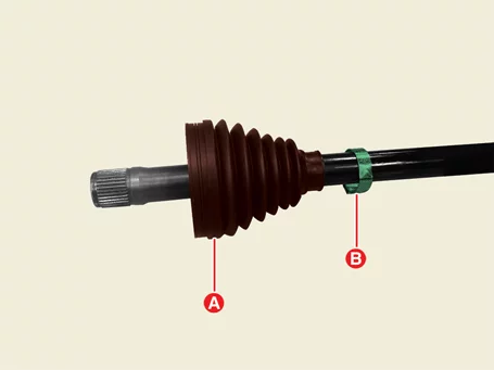
Install the transaxle side boot (A) and boot band (B) on the driveshaft.
|
| 2. |
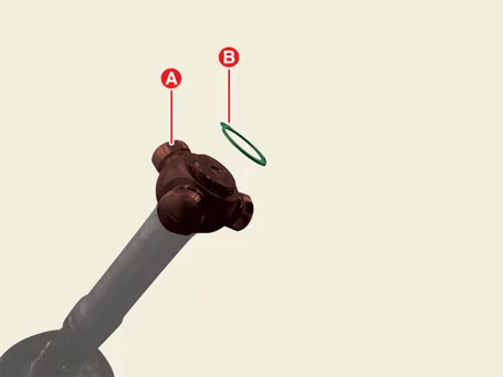
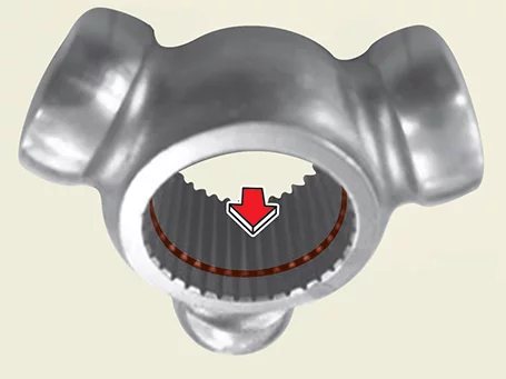
Install the spider assembly (A) and snap ring (B) to the driveshaft spline.
|
| 3. |
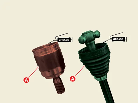
Apply specified grease inside the joint housing (A) and boot (B).
|
| 4. |
Install the bearings (A) to the spider assembly.
|
| 5. |
Install the transaxle side joint housing (A) and stopper ring (B) to the driveshaft.
|
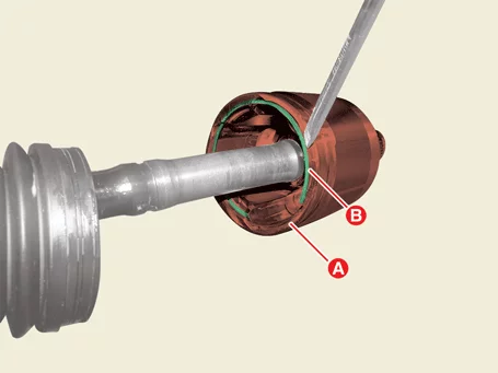
| 6. |
Install the boot (A) to the joint housing.
|
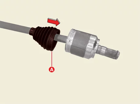
| 7. |
Install the large diameter boot band using the SST (0K495 - 2W000).
|
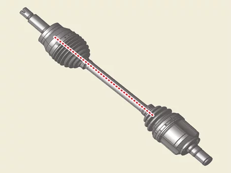
| 8. |
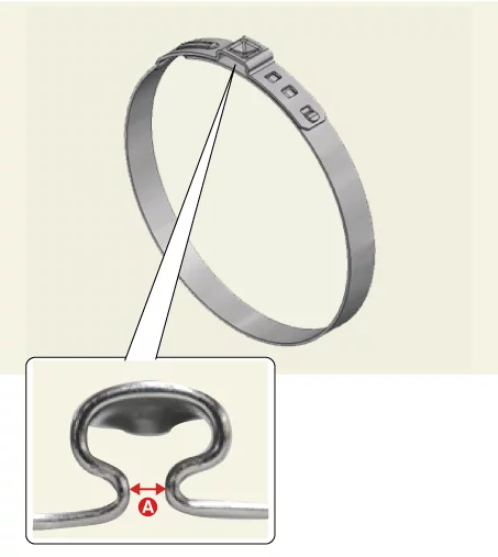
Install the small diameter boot band using the SST (0K495 - C5000).
|
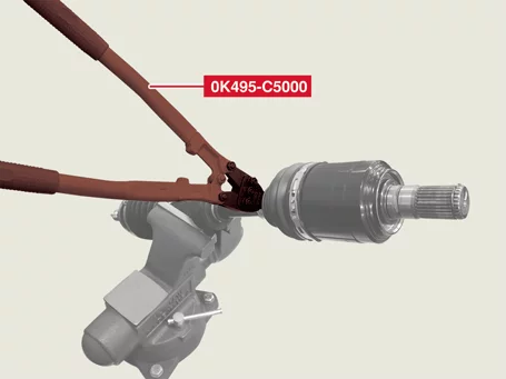
| 9. |
Install the front driveshaft.
(Refer to Driveshaft Assembly - "Front Driveshaft")
|
Joint Assembly (Wheel side) Components and Components Location
| Component |
| 1. Wheel Side Joint Housing 2. Circlip (Wheel Side) 3. Large Diameter Boot Band (Wheel Side) 4. Boot (Wheel Side) 5. Small Diameter Boot Band (Wheel Side) 6. Shaft |
7. Small Diameter Boot Band (Transaxle Side) 8. Boot (Transaxle Side) 9. Large Diameter Boot Band (Transaxle Side) 10. Spider Assembly 11. Snap Ring 12. Transaxle Side Joint Housing 13. Circlip (Transaxle Side) |
| 1. Inner Shaft Assembly 2. Transaxle Side Joint Housing 3. Stopper Ring 4. Spider Assembly Bearing 5. Snap Ring 6. Spider Assembly 7. Large Diameter Boot Band (Transaxle Side) 8. Boot |
9. Small Diameter Boot Band (Transaxle Side) 10. Shaft 11. Circlip (Wheel Side) 12. Small Diameter Boot Band (Wheel Side) 13. Boot 14. Large Diameter Boot Band (Wheel Side) 15. Wheel Side Joint Housing |
| 1. Inner Shaft Assembly 2. Transaxle Side Joint Housing 3. Stopper Ring 4. Spider Assembly Bearing 5. Snap Ring 6. Spider Assembly 7. Large Diameter Boot Band (Transaxle Side) 8. Boot |
9. Small Diameter Boot Band (Transaxle Side) 10. Shaft 11. Circlip (Wheel Side) 12. Small Diameter Boot Band (Wheel Side) 13. Boot 14. Large Diameter Boot Band (Wheel Side) 15. Wheel Side Joint Housing |
Joint Assembly (Wheel side) Removal
| Special Service Tool |
|
Tool Name / Number |
Illustration |
Description |
|
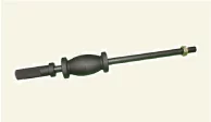
Sliding hammer 09526 - 11100 |
|
Used for removal of CV joint (Used with 0K495 - C5200) |
|
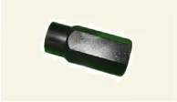
Adaptor 0K495 - C5200 |
|
Used for removal of CV joint (Used with 09526 - 11100) |
| Removal |
| 1. |
Remove the front driveshaft.
(Refer to Driveshaft Assembly - "Front Driveshaft")
|
| 2. |
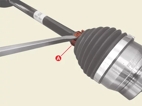
Remove the small diameter boot band (A) using the flat-head screwdriver.
|
| 3. |
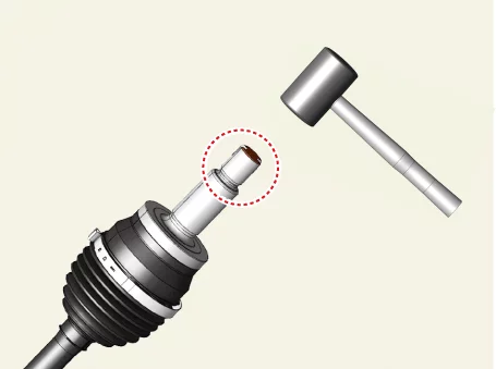
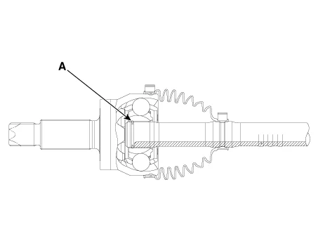
Hammer the joint spline upper side 2 - 3 times with a plastic hammer.
|
| 4. |
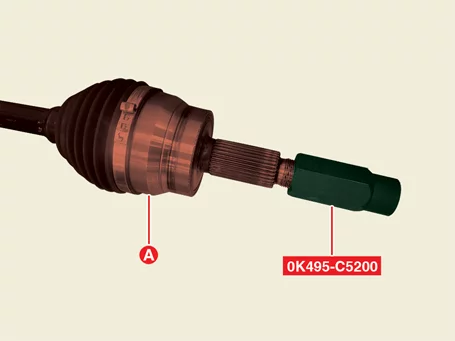
Install the SST (0K495 - C5200) on the driveshaft spline (A).
|
| 5. |
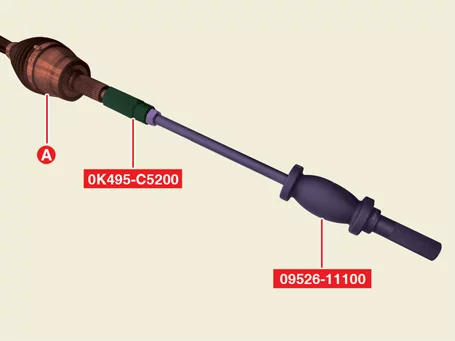
Secure the driveshaft using the vise and remove the joint assembly (A) using SST (09526 - 11100).
|
| 6. |
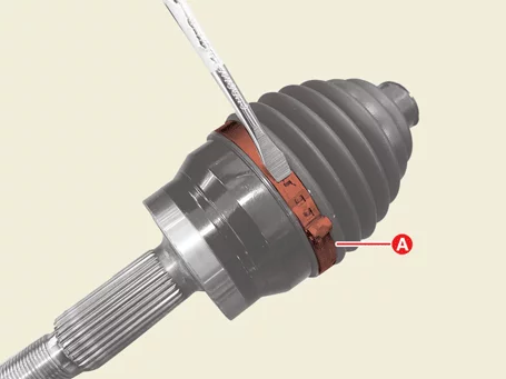
Remove the large diameter boot band (A) using a flat-head screwdriver or a remover.
|
| 7. |
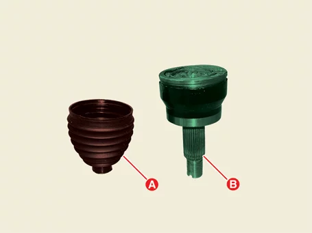
Separate the joint boot (A) and joint assembly (B).
|
| 8. |
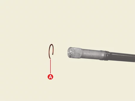
Remove the circlip (A) from the driveshaft.
|
Joint Assembly (Wheel side) Inspection
| Inspection |
| 1. |
Check spline (A) for damage / wear / crack.
|
| 2. |
Check the boot for water or foreign objects.
|
| 3. |
Check joint assembly for damage / wear / crack and rust.
|
| 4. |
Replace any defective parts.
|
Joint Assembly (Wheel side) Installation
| Special Service Tool |
|
Tool Name / Number |
Illustration |
Description |
|
Band installer 0K495 - C5000 |
|
Used for installing ear type boot band(Sharing handle with 0K495 - 2W000) |
| Installation |
|
| 1. |
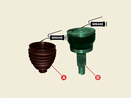
Apply specified grease inside the joint housing (A) and boot (B).
|
| 2. |
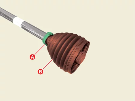
Pre-install the wheel side boot band (A) and boot (B) on the driveshaft.
|
| 3. |
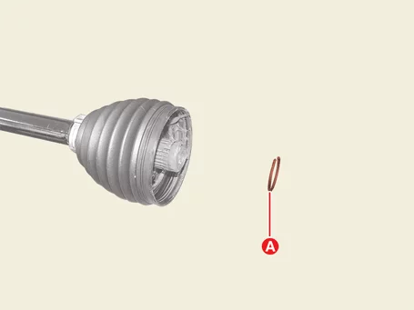
Install the circlip (A) to the driveshaft.
|
| 4. |
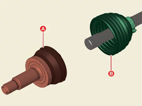
Install the wheel side joint (A) to the boot (B).
|
| 5. |
Hammer the joint spline upper side 2 - 3 times with a plastic hammer.
|
| 6. |
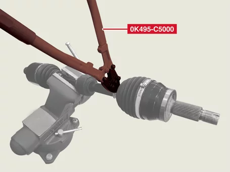
Install the large diameter boot band using the SST (0K495 - C5000).
|
| 7. |
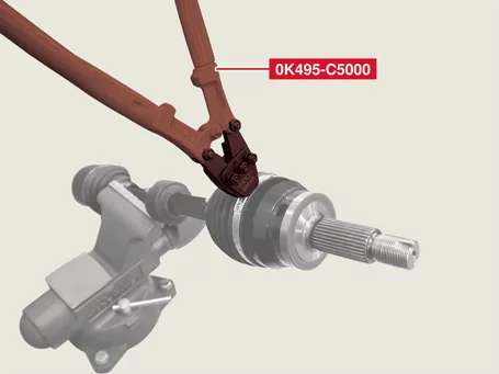
Install the small diameter boot band using the SST (0K495 - C5000).
|
| 8. |
Install the front driveshaft.
(Refer to Driveshaft Assembly - "Front Driveshaft")
|


Other information:
Kia Seltos SP2 (2021-2026) Service Manual: Manual Speed Limit Assist (MSLA)
Speed Limit indicator Set speed Manual Speed Limit Assist allows the Kia Seltos driver to set a speed limit when they do not want the vehicle to exceed a specific speed. If the vehicle speed goes above the preset limit, MSLA will operate. The set speed limit will blink and a warning chime will sound until the Kia Seltos returns to a speed within the selected limit.After selecting the correct child seat for your child, check that it fits properly in the Kia Seltos seating position where it will be used. Follow all instructions provided by the child restraint manufacturer when installing the seat. These general steps can help when installing a CRS in your Kia Seltos: Properly secure the child restraint to the vehicle.