
Kia Seltos SP2 (2021-2026) Service Manual / Driveshaft and Axle / Rear Axle Assembly
Kia Seltos: Driveshaft and Axle / Rear Axle Assembly
Contents:
- Components and Components Location
- Rear Hub Assembly Removal and Installation - 2WD
- Rear Hub Assembly Removal and Installation - 4WD
- Rear Hub Assembly Inspection
- Rear Dust Cover Removal and Installation - 2WD
- Rear Dust Cover Removal and Installation - 4WD
- Rear Dust Cover Inspection
- Rear Carrier - 4WD Removal and Installation
- Rear Carrier - 4WD Inspection
Components and Components Location
| Component |
| 2WD - CTBA |
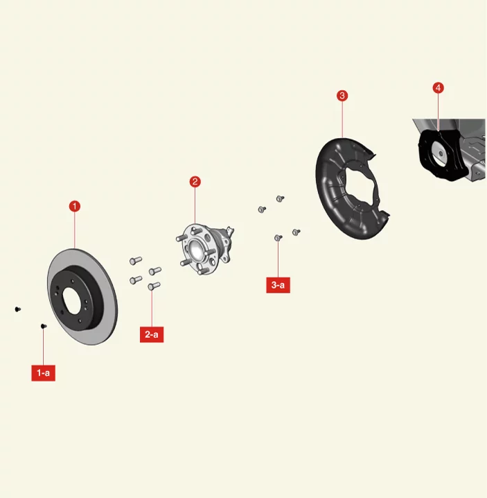
| 1. Rear Brake Disc 1-a. 4.9 - 5.9 N·m (0.5 - 0.6 kgf·m, 3.6 - 4.3 lb·ft, 43.4 - 52.1 lb·in) 2. Rear Hub Assembly 2-a. 63.7 - 73.5 N·m (6.5 - 7.5 kgf·m, 47 - 54.2 lb·ft) |
3. Rear Dust Cover 3-a. 24.5 - 34.3 N·m (2.5 - 3.5 kgf·m, 18.1 - 25.3 lb·ft) 4. Rear Knuckle |
| 4WD - Multi Link |
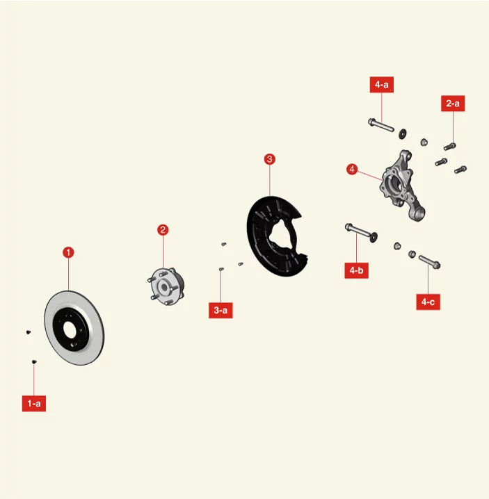
| 1. Rear Brake Disc 1-a. 4.9 - 5.9 N·m (0.5 - 0.6 kgf·m, 3.6 - 4.3 lb·ft, 43.4 - 52.1 lb·in) 2. Rear Hub Assembly 2-a. 88.3 - 107.9 N·m (9.0 - 11.0 kgf·m, 65.1 - 79.6 lb·ft) 3. Rear Dust Cover 3-a. 6.9 - 10.8 N·m (0.7 - 1.1 kgf·m, 5.1 - 8.0 lb·ft) |
4. Rear Carrier 4-a. 137.3 - 156.9 N·m (14.0 - 16.0 kgf·m, 101.3 - 115.7 lb·ft) 4-b. 117.7 - 132.4 N·m (12.0 - 13.5 kgf·m, 86.8 - 97.6 lb·ft) 4-c. 117.7 - 132.4 N·m (12.0 - 13.5 kgf·m, 86.8 - 97.6 lb·ft) |
Rear Hub Assembly Removal and Installation - 2WD
| Removal |
| 1. |
Remove the rear wheel and tires.
(Refer to Suspension System - "Wheel")
|
| 2. |
Remove the rear brake disc.
(Refer to Brake System - "Rear Brake Disc")
|
| 3. |
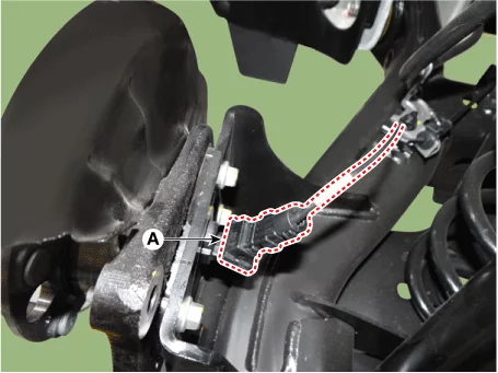
Remove the rear wheel speed sensor (A).
|
| 4. |
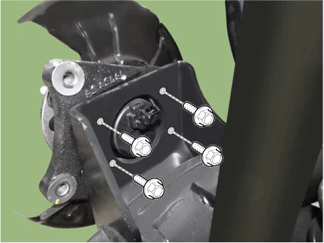
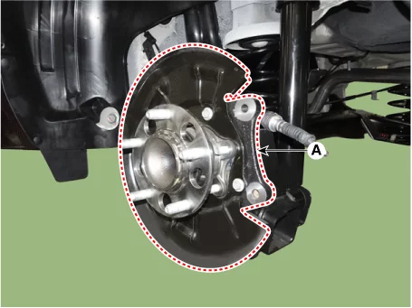
Remove the rear hub assembly and dust cover (A) after removing the rear hub assembly bolts.
|
| Installation |
| 1. |
Install in reverse order of removal.
|
Rear Hub Assembly Removal and Installation - 4WD
| Special Service Tool |
|
Tool Name / Number |
Illustration |
Description |
|
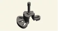
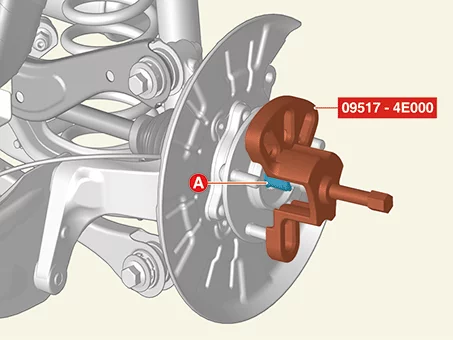
CV joint puller 09517 - 4E000 |
|
Used for removal of CV joint |
| Removal |
| 1. |
Remove the rear brake disc.
(Refer to Brake System - "Rear Brake Disc")
|
| 2. |
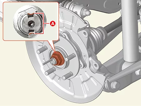
Unlock the rear driveshaft lock nut caulking (A), by hammering on a chisel or suitable tool.
|
| 3. |
Remove the rear driveshaft lock nut (A).
|
| 4. |
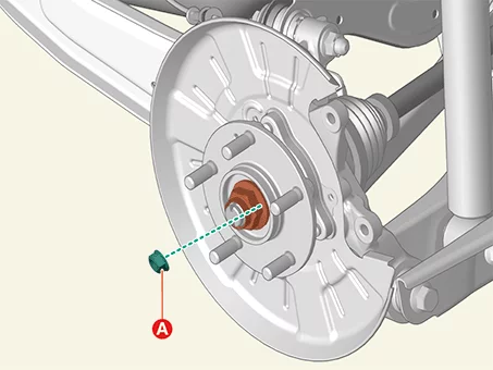
Separate the rear driveshaft (A) from the rear hub assembly using the SST (09517 - 4E000).
|
| 5. |
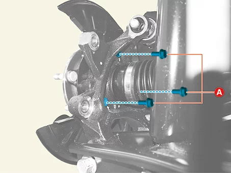
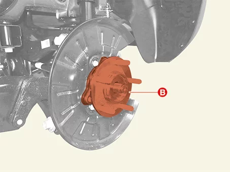
Remove the rear hub assembly (B) after removing the rear hub assembly bolts (A).
|
| Installation |
| 1. |
Install in reverse order of removal.
|
Rear Hub Assembly Inspection
| Inspection |
| 1. |
Check the rear hub assembly for wear and damage.
|
Rear Dust Cover Removal and Installation - 2WD
| Removal |
| 1. |
Remove the rear hub assembly.
(Refer to Rear Axle Assembly - "Rear Hub Assembly")
|
| 2. |
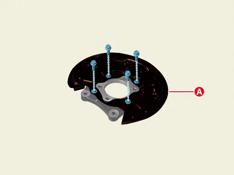
Remove the rear dust cover (A) after removing the bolts.
|
| Installation |
| 1. |
Install in reverse order of removal.
|
Rear Dust Cover Removal and Installation - 4WD
| Removal |
| 1. |
Remove the rear hub assembly.
(Refer to Rear Axle Assembly - "Rear Hub Assembly")
|
| 2. |
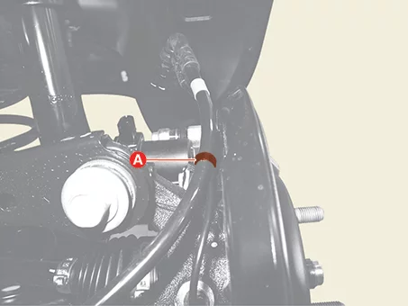
Remove the EPB extension wire clip (A) from the dust cover.
|
| 3. |
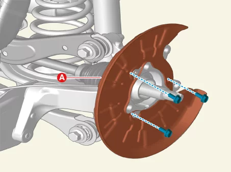
Remove the rear dust cover (A) after removing the bolts.
|
| Installation |
| 1. |
Install in reverse order of removal.
|
Rear Dust Cover Inspection
| Inspection |
| 1. |
Check the rear dust cover for scratches or damage.
|
Rear Carrier - 4WD Removal and Installation
| Removal |
If a transmission jack is used with a two-post lift, do not lift the vehicle too much. The center gravity
of the vehicle may change and fall.
|

| 1. |
Remove the rear dust cover.
(Refer to Rear Axle Assembly - "Rear Dust Cover")
|
| 2. |
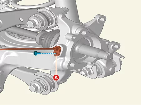
Separate the rear wheel speed sensor (A) after removing the bolt.
|
| 3. |
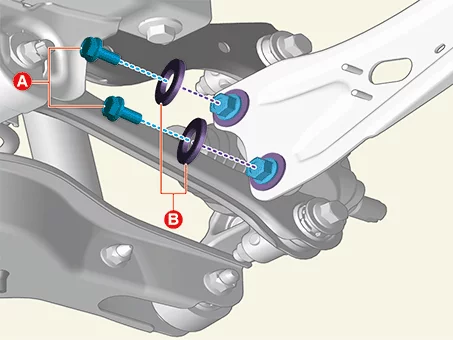
Separate the rear trailing arm from the rear carrier after removing the bolt (A) and washer (B).
|

| 4. |
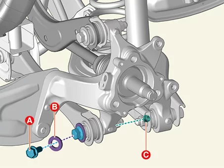
Separate the rear assist arm from the rear carrier after removing the bolt (A), washer (B), and nut (C).
|

| 5. |
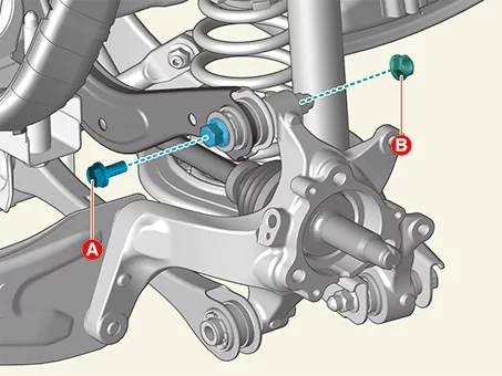
Separate the rear upper arm from the rear carrier after removing the bolt (A) and nut (B).
|
| 6. |
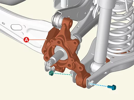
Remove the rear carrier (A) after removing the bolt and nut.
|
| Installation |
| 1. |
Install in reverse order of removal.
|
| 2. |
Check the alignment.
(Refer to Suspension System - "Alignment")
|
Rear Carrier - 4WD Inspection
| Inspection |
| 1. |
Check the rear carrier for cracks.
|

