
Kia Seltos SP2 (2021-2026) Service Manual / Engine Mechanical System / Engine and Transaxle Assembly
Kia Seltos: Engine Mechanical System / Engine and Transaxle Assembly
Contents:
- Engine Cover Removal and Installation
- Engine Room Under Cover Removal and Installation
- Engine Mounting Components and Components Location
- Engine Mounting Removal and Installation
- Engine and Transaxle Assembly Removal
- Engine and Transaxle Assembly Installation
Engine Cover Removal and Installation
| Removal |
| 1. |
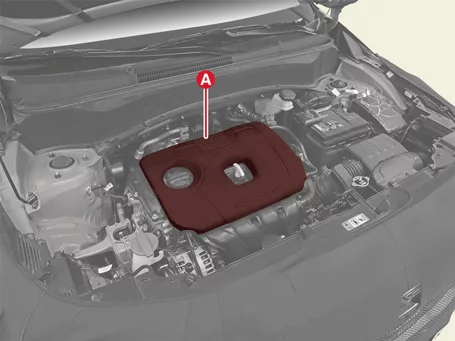
Remove the engine cover (A).
|

| Installation |
| 1. |
Install in reverse order of removal.
|
Engine Room Under Cover Removal and Installation
| Removal |
| 1. |
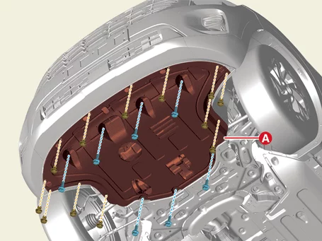
Remove the engine room under cover (A) after removing the fastener and bolts.
|
| Installation |
| 1. |
Install in reverse order of removal.
|
Install the Engine room under cover to the specified torque.
|
Engine Mounting Components and Components Location
| Component |
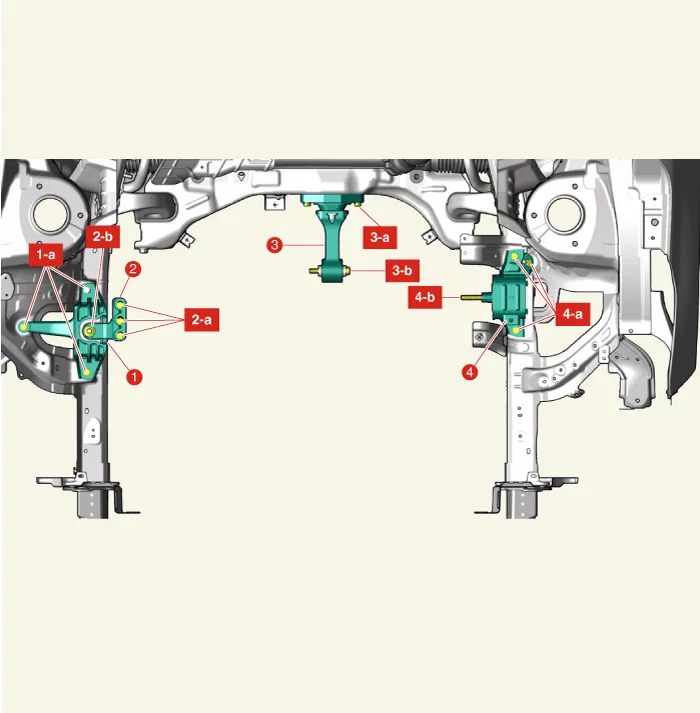
| 1. Engine Mounting Bracket 1-a. 49.0 - 63.7 N·m (5.0 - 6.5 kgf·m, 36.2 - 47 lb·ft) 2. Engine Mounting Support Bracket. 2-a. 78.5 - 98.1 N·m (8.0 - 10.0 kgf·m, 57.9 - 72.3 lb·ft) 2-b. 78.5 - 98.1 N·m (8.0 - 10.0 kgf·m, 57.9 - 72.3 lb·ft) |
3. Roll Rod Bracket 3-a. 49.0 - 63.7 N·m (5.0 - 6.5 kgf·m, 36.2 - 47 lb·ft) 3-b. 107.9 - 127.5 N·m (11.0 - 13.0 kgf·m , 79.6 - 94.0 lb·ft) 4. IVT Mounting Bracket 4-a. 49.0 - 63.7 N·m (5.0 - 6.5 kgf·m , 36.2 - 47.0 lb·ft) 4-b. 98.1 - 117.7 N·m (10.0 - 12.0 kgf·m, 72.3 - 86.8 lb·ft) |
Engine Mounting Removal and Installation
| Removal |
Engine Mounting Bracket
| 1. |
Remove the engine room under cover.
(Refer to Engine and Transaxle Assembly - "Engine Room Under
Cover")
|
| 2. |
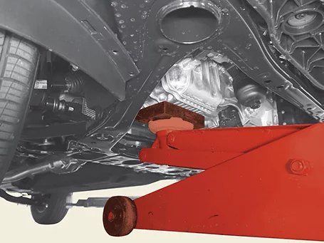
Install the jack to the edge of oil pan to support the engine.
|
| 3. |
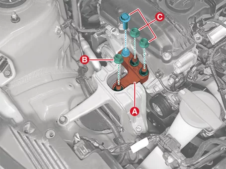
Remove the engine mounting support bracket (A), after removing the bolt and nuts.
|
| 4. |
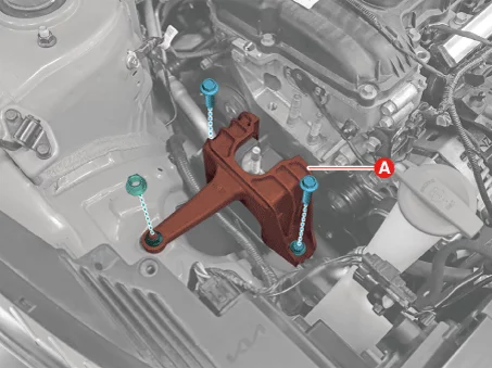
Remove the engine mounting bracket (A), after removing the bolt and nut.
|
Roll Rod Bracket
| 1. |
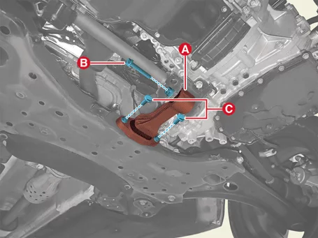
Remove the roll rod bracket (A) after removing the bolts (B, C).
|
| 2. |
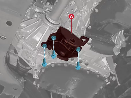
Remove the roll rod mounting support bracket (A), after removing the bolts.
|
IVT Mounting Bracket
| 1. |
Disconnect the battery negative ( - ) terminal.
|
| 2. |
Remove the air duct and air cleaner assembly.
(Refer to Intake and Exhaust System - "Air Cleaner")
|
| 3. |
Remove the battery.
(Refer to Engine Electrical System - "Battery")
|
| 4. |
Remove the Engine Control Module (ECM).
(Engine Control / Fuel System - "Engine Control Module (ECM)")
|
| 5. |
Remove the battery tray.
(Refer to Engine Electrical System - "Battery")
|
| 6. |
Remove the LH front wheel guard.
(Refer to Body - "Front Wheel Guard")
|
| 7. |
Remove the engine room under cover.
(Refer to Engine and Transaxle Assembly – "Engine Room Under
Cover")
|
| 8. |
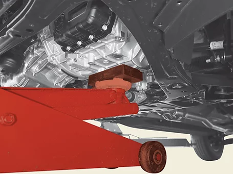
Support the IVT securely using a jack.
|
| 9. |
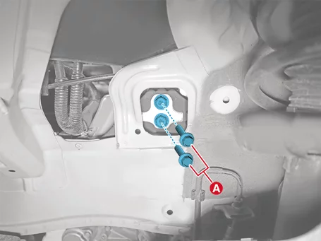
Remove the IVT mounting bracket bolts (A).
|
| 10. |
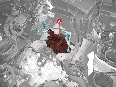
Remove the IVT mounting bracket (A) after removing bolts and nut.
|
| Installation |
| Engine Mounting Bracket |
| 1. |
Install in reverse order of removal.
|
| Roll Rod Bracket |
| 1. |
Install in reverse order of removal.
|
| IVT Mounting Bracket |
| 1. |
Install in reverse order of removal.
|
Engine and Transaxle Assembly Removal
| Removal |
|
Mark all wiring and hoses to prevent incorrect connections.
|

| 1. |
Release the residual pressure in fuel line.
(Refer to Fuel Delivery System - "Release Residual Pressure in Fuel
Line")
|
| 2. |
Disconnect the battery negative ( - ) terminal.
|
| 3. |
Remove the engine cover.
(Refer to Engine And Transaxle Assembly - "Engine Cover")
|
| 4. |
Remove the air duct and air cleaner assembly.
(Refer to Intake and Exhaust System - "Air Cleaner")
|
| 5. |
Remove the battery.
(Refer to Engine Electrical System - "Battery")
|
| 6. |
Remove the Engine Control Module (ECM).
(Refer to Engine Control / Fuel System - "Engine Control Module
(ECM)")
|
| 7. |
Remove the battery tray.
(Refer to Engine Electrical System - "Battery")
|
| 8. |
Remove the engine room under cover.
(Refer to Engine and Transaxle Assembly – "Engine Room Under
Cover")
|
| 9. |
Drain the coolant.
(Refer to Cooling System - "Coolant")
|
| 10. |
Disconnect the A/C compressor high pressure pipe and low pressure pipe.
(Refer to Heating, Ventilation and Air Conditioning -
"Compressor")
|
| 11. |
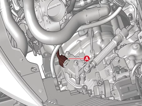
Disconnect the position switch connector (A).
|
| 12. |
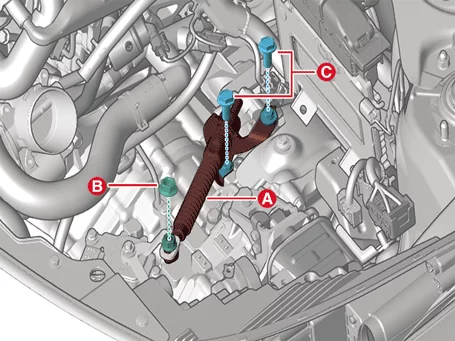
Remove the shift cable (A) after removing the bolts (C) and nut (B).
|
| 13. |
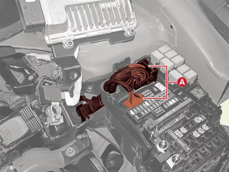
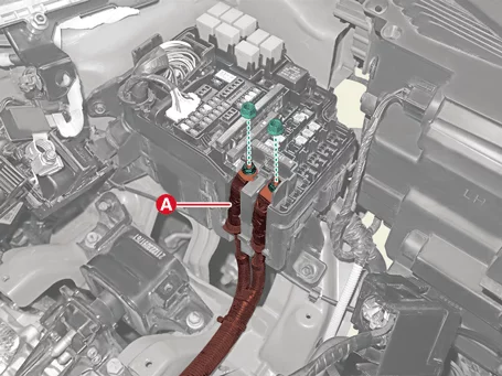
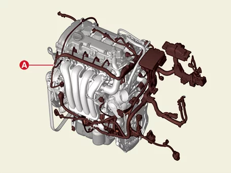
Disconnect the main wiring harness from the engine room.
|
| 14. |
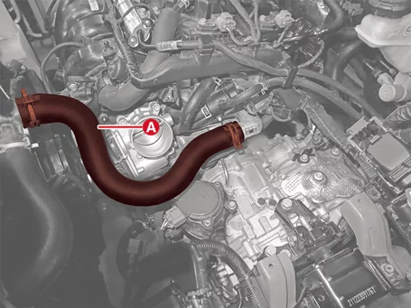
Separate the radiator upper hose (A) after releasing the clamp.
|
| 15. |
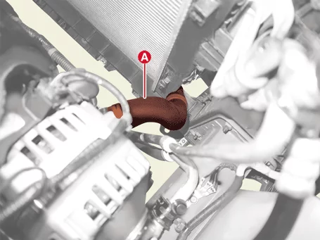
Separate the radiator lower hose (A) after releasing the clamp.
|
| 16. |
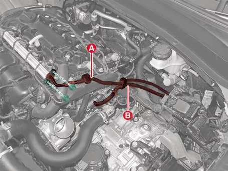
Disconnect the fuel hose (A) and Purge Control Solenoid Valve (PCSV) hose (B) after removing nuts.
|
| 17. |
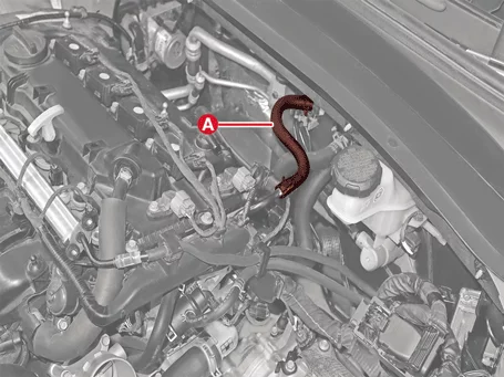
Release the clamp, and then disconnect the brake booster vacuum hose (A).
|
| 18. |
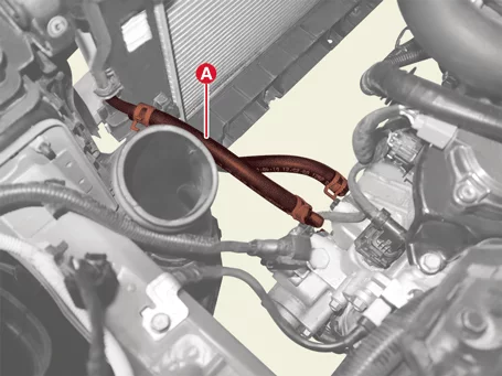
Separate the IVTF cooler hoses (A) after releasing the clamp.
|
| 19. |
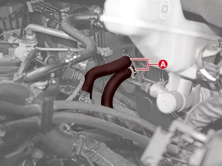
Release the clamp, and then disconnect the heater hose (A).
|
| 20. |
Remove the front muffler.
(Refer to Intake And Exhaust System – "Muffler")
|
| 21. |
Remove the roll rod bracket (A) after removing the bolts (B, C).
|
| 22. |
Remove the roll rod mounting support bracket (A), after removing the bolts.
|
| 23. |
Remove the front sub-frame.
(Refer to Suspension System – “Front Sub Frame”)
|
| 24. |
Remove the propeller shaft.(AWD type)
(Refer to All Wheel Drive (AWD) System - "Propeller Shaft")
|
| 25. |
Remove the front driveshaft.
(Refer to Driveshaft and Axle - "Front Driveshaft")
|
| 26. |
Support the engine and transaxle assembly securely with a follower jack.
|
| 27. |
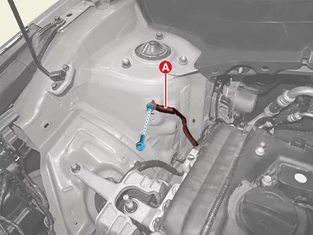
Separate the engine ground cable (A) after removing the bolt.
|
| 28. |
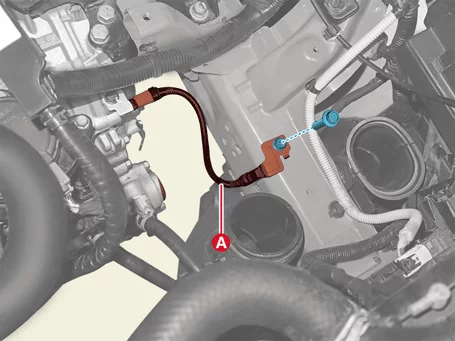
Disconnect the transaxle grounding cable (A) after removing the bolt.
|
| 29. |
Remove the engine mounting support bracket (A), after removing the bolt and nuts.
|
| 30. |
Remove the LH front wheel guard.
(Refer to Body - "Front Wheel Guard")
|
| 31. |
Remove the IVT mounting bracket bolts (A).
|
| 32. |
Remove the engine and transaxle assembly (A) by lifting vehicle.
|
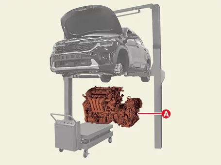
Engine and Transaxle Assembly Installation
| Installation |
| 1. |
Install in reverse order of removal.
|
| 2. |
Fill the coolant.
(Refer to Cooling System - "Coolant")
|
After installation is complete, do the following.
| • |
Check for fuel leaks.
|
| – |
After assembling the fuel line, turn on the key (at this time, do not start the engine) and drive the
fuel pump for about 2 seconds to create pressure in the fuel line.
|
| – |
After repeating the above operation 2-3 times, check that there is no fuel leak in the fuel line.
|
| • |
After cleaning the battery terminals and cable terminals with sandpaper, assemble them
|


Other information:
Kia Seltos SP2 (2021-2026) Service Manual: Highway Driving Assist (HDA)
Highway Driving Assist (HDA) in the Kia Seltos is designed to help detect vehicles and lane markings ahead. When operating on supported highways, it can help maintain distance from the vehicle ahead, maintain the set speed, and help keep the Kia Seltos centered in the lane. NOTICE HDA is available only on controlled-access roads of certain highways.Kia Seltos SP2 (2021-2026) Service Manual: Vehicle load limit
The vehicle load limit for the Kia Seltos is shown on the tire and loading information label located on the driver's door area. Tire and loading information label The label on the driver's door sill shows the original tire size, the recommended cold tire pressures, the maximum number of occupants, and the vehicle capacity weight for your Kia Seltos.