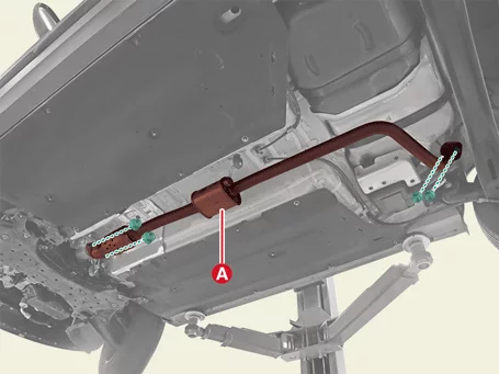
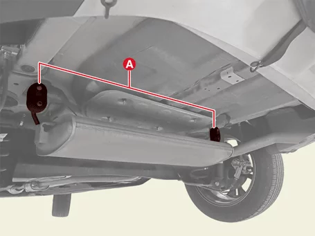
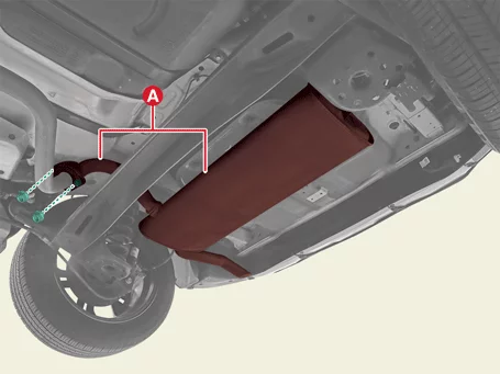
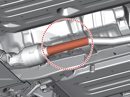
Owner's library Kia Seltos Manuals Owner's manual pages, service notes, maintenance references and practical Kia Seltos help in one clean library.

Kia Seltos reference pages

Manuals, maintenance notes and quick owner help.

Find Kia Seltos operating instructions, warning light explanations, service information and owner guidance without digging through a full PDF.

Kia Seltos: Engine Mechanical System / Intake and Exhaust System

Contents:

Air Cleaner Components and Components Location

Component

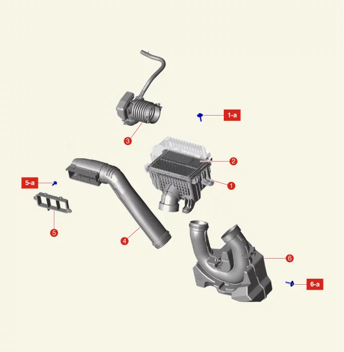
Engine Mechanical System — Intake and Exhaust System / Air Cleaner / Components and Components Location / Component illustration

1. Air Cleaner Assembly
1-a. 3.9 - 5.9 N·m (0.4 - 0.6 kgf·m, 2.9 - 4.3 lb·ft, 34.7 - 52.1 lb·in)
2. Air Cleaner Filter
3. Air Intake Hose
4. Air Duct
5. Air Intake Shield
5-a. 3.9 - 5.9 N·m (0.4 - 0.6 kgf·m, 2.9 - 4.3 lb·ft)
6. Resonator
6-a. 3.9 - 5.9 N·m (0.4 - 0.6 kgf·m, 2.9 - 4.3 lb·ft)

Air Cleaner Removal and Installation

Removal
Air Cleaner Assembly
1.
Disconnect the battery negative ( - ) terminal.
2.
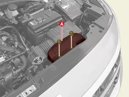
Remove the air duct (A) after removing the fastener.

Engine Mechanical System — Intake and Exhaust System / Air Cleaner / Removal and Installation / Removal illustration

3.
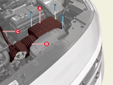
Remove the air cleaner assembly.
(1)
Separate the air intake hose (B) after releasing the clamp.
(2)
Separate the breather hose (C) after releasing the clamp.
(3)
Remove the air cleaner assembly (A) after removing the bolts.

Tightening torque :
3.9 - 5.9 N·m (0.4 - 0.6 kgf·m, 2.9 - 4.3 lb·ft, 34.7 - 52.1 lb·in)

Engine Mechanical System — Intake and Exhaust System / Air Cleaner / Removal and Installation / Removal illustration

Air Cleaner Filter Replacement
1.
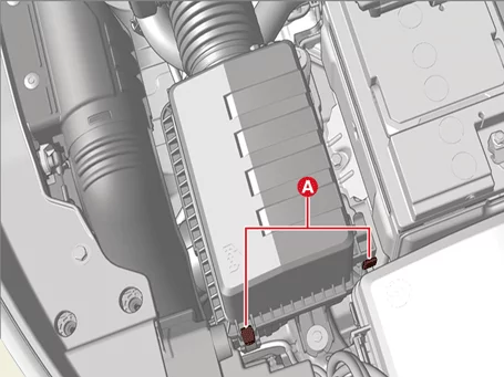
Open the air cleaner element cover by unlocking the clamp.

Engine Mechanical System — Intake and Exhaust System / Air Cleaner / Removal and Installation / Removal illustration

2.
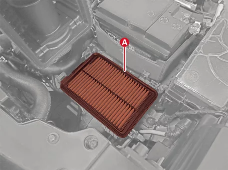
Replace the air cleaner filter (A) with a new one by lifting the air cleaner filter cover.

Engine Mechanical System — Intake and Exhaust System / Air Cleaner / Removal and Installation / Removal illustration

Note    
If the inside of the air cleaner assembly is contaminated, clean it and replace the element.
3.
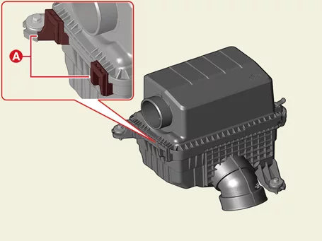
Insert the hinge (A) and engage the clamp when mounting the air cleaner cover.

Engine Mechanical System — Intake and Exhaust System / Air Cleaner / Removal and Installation / Removal illustration

Air Intake Shield
1.
Remove the air duct (A) after removing the fasteners.

Engine Mechanical System — Intake and Exhaust System / Air Cleaner / Removal and Installation / Removal illustration

2.
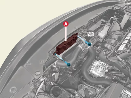
Remove the air intake shield (A) after removing the bolts.

Tightening torque :
3.9 - 5.9 N·m (0.4 - 0.6 kgf·m, 2.9 - 4.3 lb·ft, 34.7 - 52.1 lb·in)

Engine Mechanical System — Intake and Exhaust System / Air Cleaner / Removal and Installation / Removal illustration

Resonator
1.
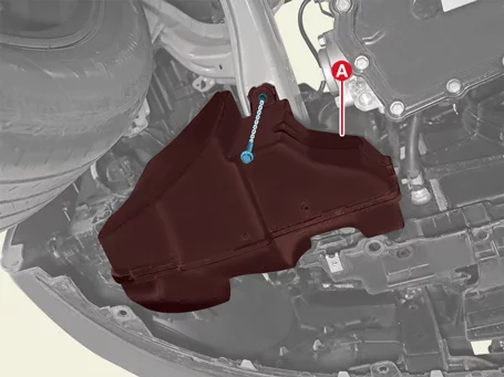
Remove the engine room under cover.
(Refer to Engine and Transaxle Assembly - "Engine Room Under Cover")
2.
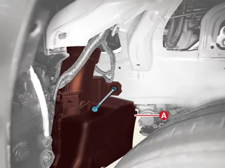
Remove the resonator (A) after removing the bolt.

Tightening torque :
3.9 - 5.9 N·m (0.4 - 0.6 kgf·m, 2.9 - 4.3 lb·ft, 34.7 - 52.1 lb·in)

Engine Mechanical System — Intake and Exhaust System / Air Cleaner / Removal and Installation / Removal illustration

Engine Mechanical System — Intake and Exhaust System / Air Cleaner / Removal and Installation / Removal illustration

Installation
Air Cleaner Assembly
1.
Install in reverse order of removal.
Note    
Install the air cleaner assembly to the specified torque.
Air Cleaner Filter Replacement
1.
Close the air cleaner cover by hooking the clamps.
Air Intake Shield
1.
Install in reverse order of removal.
Note    
Install the air intake shield to the specified torque.
Resonator
1.
Install in reverse order of removal.
Note    
Install the resonator to the specified torque.

Intake Manifold Components and Components Location

Component

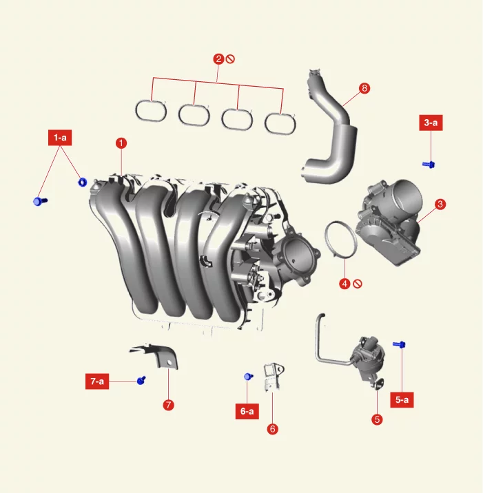
Engine Mechanical System — Intake and Exhaust System / Intake Manifold / Components and Components Location / Component illustration

1. Intake Manifold
1-a. 18.6 - 23.5 N·m (1.9 - 2.4 kgf·m, 13.7 - 17.4 lb·ft)
2. Intake Manifold Gasket
3. Electronic Throttle Control (ETC) Body
3-a. 9.8 - 11.8 N·m (1.0 - 1.2 kgf·m, 7.2 - 8.7 lb·ft)
4. Electronic Throttle Control (ETC) Body Gasket
5. Variable Intake Solenoid (VIS) Actuator
5-a. 9.8 - 11.8 N·m (1.0 - 1.2 kgf·m, 7.2 - 8.7 lb·ft)
6. Manifold Absolute Pressure Sensor & Intake Air Temperature Sensor (MAPS & IATS)
6-a. 9.8 - 11.8 N·m (1.0 - 1.2 kgf·m, 7.2 - 8.7 lb·ft)
7. Intake Manifold Stay
7-a. 18.6 - 23.5 N·m (1.9 - 2.4 kgf·m, 13.7 - 17.4 lb·ft)
8. PCV Hose

Intake Manifold Removal and Installation

Removal
1.
Release the residual pressure in fuel line.
(Refer to Fuel Delivery System - "Release Residual Pressure in Fuel Line")
2.
Disconnect the battery negative ( - ) terminal.
3.
Remove the engine cover.
(Refer to Engine and Transaxle Assembly - "Engine Cover")
4.
Remove the air duct and air cleaner assembly.
(Refer to Intake and Exhaust System – "Air Cleaner")
5.
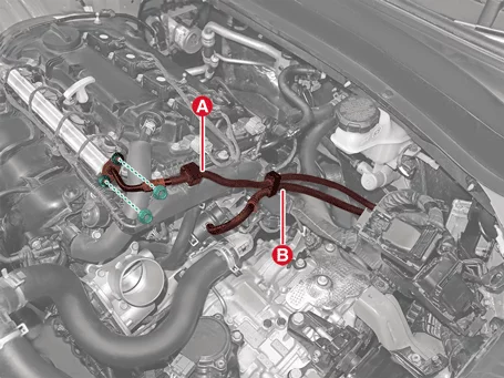
Disconnect the fuel hose (A) and Purge Control Solenoid Valve (PCSV) hose (B) after removing nuts.

Tightening torque :
8.8 - 11.8 N·m (0.9 - 1.2 kgf·m, 6.5 - 8.7 lb·ft)

Engine Mechanical System — Intake and Exhaust System / Intake Manifold / Removal and Installation / Removal illustration

6.
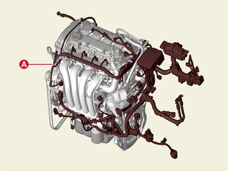
Disconnect and separate the connectors and the wiring harness (A) around the intake manifold.

Engine Mechanical System — Intake and Exhaust System / Intake Manifold / Removal and Installation / Removal illustration

7.
Remove the ETC (Electronic Throttle Control) Module.
(Refer to Engine Control System - "ETC (Electronic Throttle Control) System")
8.
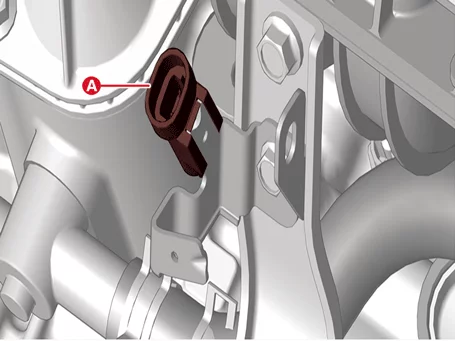
Disconnect the knock sensor connector (A) from the knock sensor bracket.

Engine Mechanical System — Intake and Exhaust System / Intake Manifold / Removal and Installation / Removal illustration

9.
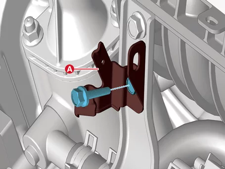
Remove the knock sensor bracket (A) after removing the bolt.

Tightening torque :
18.6 - 23.5 N·m (1.9 - 2.4 kgf·m, 13.7 - 17.4 lb·ft)

Engine Mechanical System — Intake and Exhaust System / Intake Manifold / Removal and Installation / Removal illustration

10.
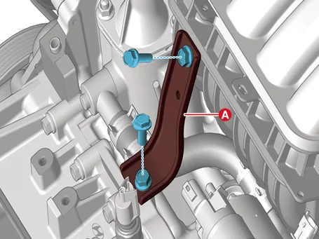
Remove the intake manifold stay (A), after removing the bolts.

Tightening torque :
18.6 - 23.5 N·m (1.9 - 2.4 kgf·m, 13.7 - 17.4 lb·ft)

Engine Mechanical System — Intake and Exhaust System / Intake Manifold / Removal and Installation / Removal illustration

11.
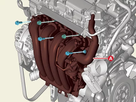
Remove the intake manifold (A) and the gasket after removing the bolts and nuts.

Tightening torque :
18.6 - 23.5 N·m (1.9 - 2.4 kgf·m, 13.7 - 17.4 lb·ft)

Engine Mechanical System — Intake and Exhaust System / Intake Manifold / Removal and Installation / Removal illustration

Note    
Do not reuse the intake manifold gasket.
Installation
1.
Install in reverse order of removal.
Note    
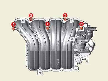
Pre-tighten the bolts and nuts in the sequence of the illustration before tightening them to the specified torque.

Engine Mechanical System — Intake and Exhaust System / Intake Manifold / Removal and Installation / Installation illustration

Exhaust Manifold Components and Components Location

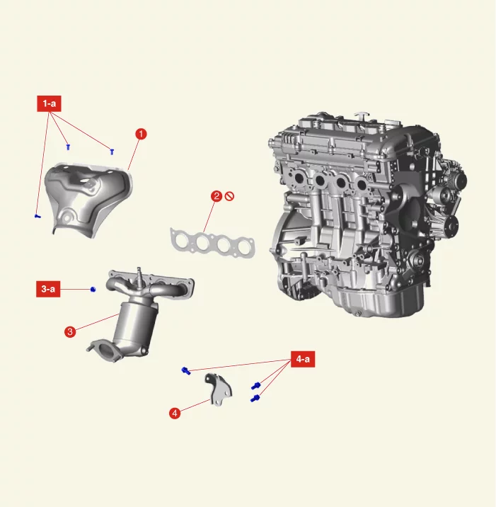
Component

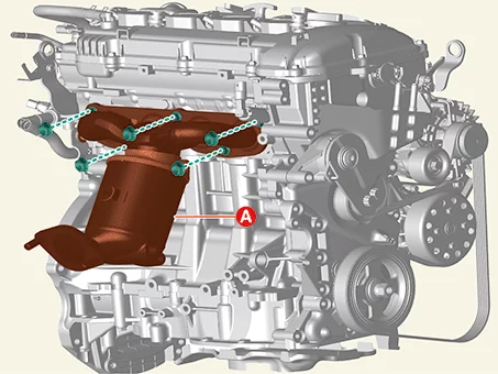
Engine Mechanical System — Intake and Exhaust System / Exhaust Manifold / Components and Components Location / Component illustration

1. Heat Protector
1-a. 9.8 - 11.8 N·m (1.0 - 1.2 kgf·m, 7.2 - 8.7 lb·ft)
2. Exhaust Manifold Gasket
3. Exhaust Manifold
3-a. 34.3 - 39.2 N·m (3.5 - 4.0 kgf·m, 25.3 - 28.9 lb·ft)
4. Exhaust Manifold Stay
4-a. 39.3 - 49.0 N·m (4.0 - 5.0 kgf·m, 29.0 - 36.1 lb·ft)

Exhaust Manifold Removal and Installation

Removal
1.
Disconnect the battery negative ( - ) terminal.
2.
Remove the engine cover.
(Refer to Engine and Transaxle Assembly - "Engine Cover")
3.
Remove the air duct and air cleaner assembly.
(Refer to Intake and Exhaust System - "Air Cleaner")
4.
Remove the front Heated Oxygen Sensor (HO2S).
(Refer to Engine Control / Fuel System - "Heated Oxygen Sensor (HO2S)")
5.
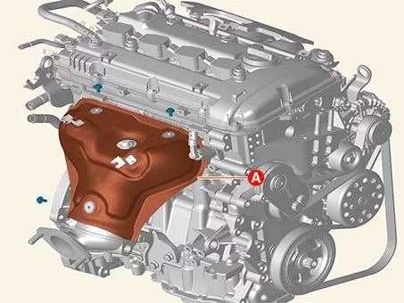
Remove the exhaust manifold heat protector (A) after removing the bolts.

Tightening torque :
9.8 - 11.8 N·m (1.0 - 1.2 kgf·m, 7.2 - 8.7 lb·ft)

Engine Mechanical System — Intake and Exhaust System / Exhaust Manifold / Removal and Installation / Removal illustration

6.
Remove the engine room under cover.
(Refer to Engine and Transaxle Assembly - "Engine Room Under Cover")
7.
Remove the front muffler.
(Refer to Intake And Exhaust System – "Muffler")
8.
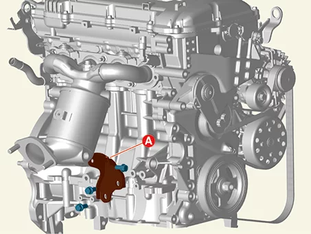
Remove the exhaust manifold stay (A) after removing the bolts.

Tightening torque :
39.2 - 49.0 N·m (4.0 - 5.0 kgf·m, 28.9 - 36.2 lb·ft)

Engine Mechanical System — Intake and Exhaust System / Exhaust Manifold / Removal and Installation / Removal illustration

9.
Remove the exhaust manifold (A) after removing the nuts.

Tightening torque :
34.3 - 39.2 N·m (3.5 - 4.0 kgf·m, 25.3 - 28.9 lb·ft)

Engine Mechanical System — Intake and Exhaust System / Exhaust Manifold / Removal and Installation / Removal illustration

10.
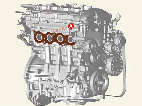
Remove the exhaust manifold gasket (A).

Engine Mechanical System — Intake and Exhaust System / Exhaust Manifold / Removal and Installation / Removal illustration

Note    
Do not reuse the gasket.
Installation
1.
Install in reverse order of removal.
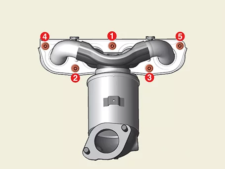
Note    
Install the exhaust manifold in the sequence as illustrated to the specified torque.

Engine Mechanical System — Intake and Exhaust System / Exhaust Manifold / Removal and Installation / Removal illustration

Muffler Components and Components Location

Component

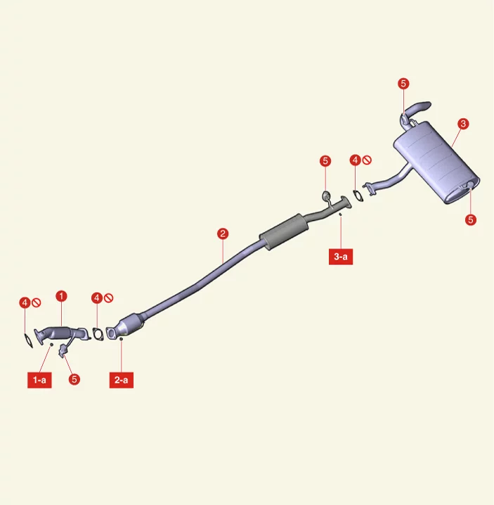
Engine Mechanical System — Intake and Exhaust System / Muffler / Components and Components Location / Component illustration

1. Front Muffler
1-a. 39.2 - 58.8 N·m (4.0 - 6.0 kgf·m, 28.9 - 43.4 lb·ft)
2. Catalytic Converter & Center Muffler Assembly
2-a. 39.2 - 58.8 N·m (4.0 - 6.0 kgf·m, 28.9 - 43.4 lb·ft)
3. Rear Muffler
4. Gasket
5. Hanger

Muffler Removal and Installation

Removal
Front Muffler
1.
Disconnect the battery negative ( - ) terminal.
2.
Remove the engine cover.
(Refer to Engine And Transaxle Assembly - "Engine Cover")
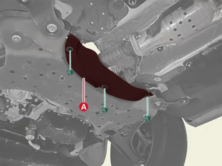
3.
Remove the heat protector (A), after removing the nut.

Tightening torque :
9.8 - 11.8 N·m (1.0 - 1.2 kgf·m, 7.2 - 8.7 lb·ft)

Engine Mechanical System — Intake and Exhaust System / Muffler / Removal and Installation / Removal illustration

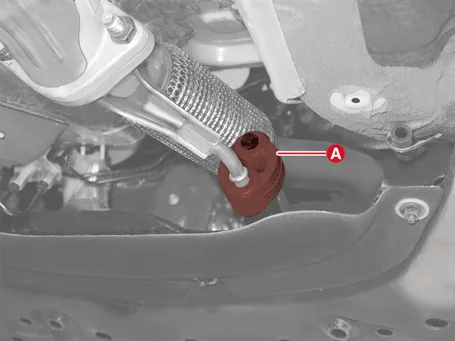
4.
Separate the rubber hanger (A).

Engine Mechanical System — Intake and Exhaust System / Muffler / Removal and Installation / Removal illustration

5.
Remove the front muffler (A) after removing the nuts.

Tightening torque :
39.2 - 58.8 N·m (4.0 - 6.0 kgf·m, 28.9 - 43.4 lb·ft)

Engine Mechanical System — Intake and Exhaust System / Muffler / Removal and Installation / Removal illustration

Catalytic Converter & Center Muffler
1.
Remove the heat protector (A).

Tightening torque :
9.8 - 11.8 N·m (1.0 - 1.2 kgf·m, 7.2 - 8.7 lb·ft)

Engine Mechanical System — Intake and Exhaust System / Muffler / Removal and Installation / Removal illustration

2.
Separate the rubber hanger (A).

Engine Mechanical System — Intake and Exhaust System / Muffler / Removal and Installation / Removal illustration

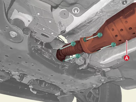
3.
Remove the catalytic converter & center muffler assembly (A) after removing the nut.

Tightening torque :
39.2 - 58.8 N·m (4.0 - 6.0 kgf·m, 28.9 - 43.4 lb·ft)

Engine Mechanical System — Intake and Exhaust System / Muffler / Removal and Installation / Removal illustration

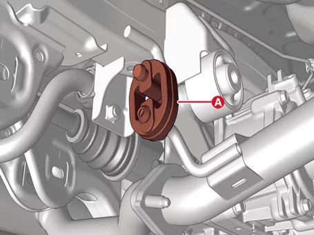
Rear Muffler
1.
Separate the rubber hanger (A).

Engine Mechanical System — Intake and Exhaust System / Muffler / Removal and Installation / Removal illustration

2.
Remove the rear muffler (A) after removing the nuts.

Tightening torque :
39.2 - 58.8 N·m (4.0 - 6.0 kgf·m, 28.9 - 43.4 lb·ft)

Engine Mechanical System — Intake and Exhaust System / Muffler / Removal and Installation / Removal illustration

Installation
Front Muffler
1.
Install in reverse order of removal.
Note    
Install the front muffler to the specified torque.
Catalytic Converter & Center Muffler
1.
Install in reverse order of removal.
Rear Muffler
1.
Install in reverse order of removal.
Note    
Install the rear muffler to the specified torque.
Replacement procedure of center muffler using clamp
Under warranty : Replace the center muffler assembly.
Out of warranty : It is available to replace the center muffler as the procedure below.
1.
Check the center muffler for deformation or damage to the part where the clamp is to be mounted.
If clamp mounting is not possible, replace with a center muffler assembly.

Engine Mechanical System — Intake and Exhaust System / Muffler / Removal and Installation / Installation illustration

2.
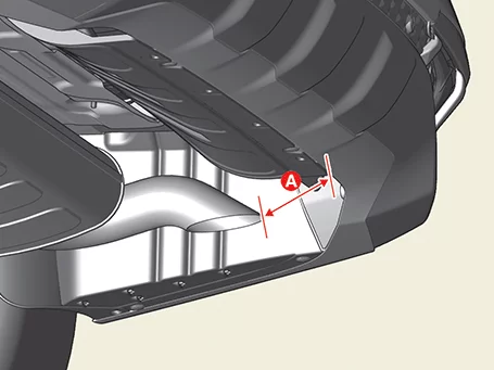
If clamps are available, measure and record the distance between the tail trim and rear bumper (A).

Engine Mechanical System — Intake and Exhaust System / Muffler / Removal and Installation / Installation illustration

3.
Separate the rubber hanger (A) from the center muffler.

Engine Mechanical System — Intake and Exhaust System / Muffler / Removal and Installation / Installation illustration

4.
Remove the center muffler (A) after removing the nuts.

Engine Mechanical System — Intake and Exhaust System / Muffler / Removal and Installation / Installation illustration

5.
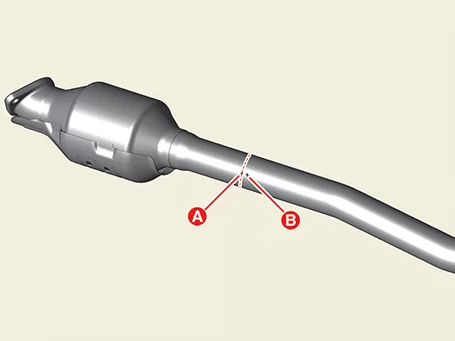
Cut the clamp tightening point of the center muffler.
–
Cut the front dent position of the muffler.
A : Front dent
B : Rear dent

Engine Mechanical System — Intake and Exhaust System / Muffler / Removal and Installation / Installation illustration

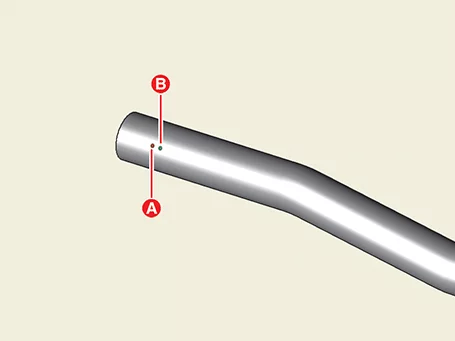
[New Muffler]
–
Cut the rear dent of the replacement muffler.
A : Front dent
B : Rear dent

Engine Mechanical System — Intake and Exhaust System / Muffler / Removal and Installation / Installation illustration

Note    
•
After tightening the fixture, remove foreign objects, rust, welding spatter and cutting residue on the cutting surface to prevent leakage and welding of the cut part of the pipe.
•
The pipe is cut vertically.
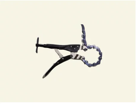
Information    
•
Use an easy-to-cut pipe cutter that is smooth and perpendicular to the cut surface.

Engine Mechanical System — Intake and Exhaust System / Muffler / Removal and Installation / Installation illustration

•
If a pipe cutter is not available, use a hacksaw as per the procedure below.
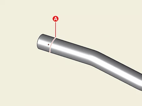
1)
Marking (A) is made around the pipe in the dent position to cut the pipe vertically.

Engine Mechanical System — Intake and Exhaust System / Muffler / Removal and Installation / Installation illustration

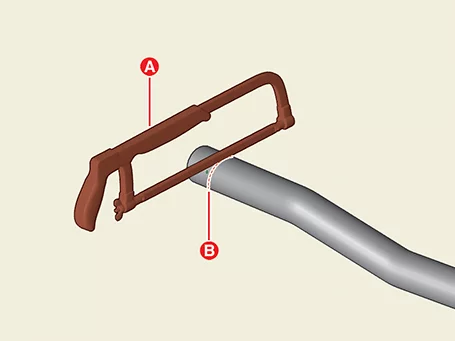
2)
Cut the pipe along the marking line (B) using a hacksaw (A).

Engine Mechanical System — Intake and Exhaust System / Muffler / Removal and Installation / Installation illustration

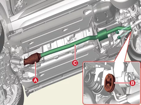
6.
Install the center muffler.
(1)
Install the catalytic converter (A).
(2)
Attach the rubber hook (B) and attach the central muffler (C).

Engine Mechanical System — Intake and Exhaust System / Muffler / Removal and Installation / Installation illustration

Note    
Replace with a new gasket upon installation.
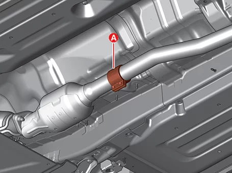
(3)
Insert and temporarily secure clamps (A) between each pipe cutout.

Engine Mechanical System — Intake and Exhaust System / Muffler / Removal and Installation / Installation illustration

(4)
Tighten the nuts on the catalytic converter and exhaust heat recovery device & center muffler to the specified torque.

Tightening torque
Nut : 39.2 - 58.8 N·m (4.0 - 6.0 kgf·m, 28.9 - 43.4 lb·ft)
Clamp : 16.7 - 27.5 N·m (1.7 - 2.8 kgf·m, 12.3 - 20.3 lb·ft)

(5)
Before removing the center muffler, check the distance between the tailpipe (or tail trim) and the rear bumper with a measurement record and realign if there is a problem.
Note    
If the position of the tail pipe is different from the initial state, the bumper may be damaged due to interference, noise, and heat between the tail pipe and the rear bumper.
(6)
Tighten the clamp nut several times evenly.

Tightening torque :
17.7 - 24.5 N·m (1.8 - 2.5 kgf·m, 13.0 - 18.1 lb·ft)

Engine Mechanical System — Intake and Exhaust System / Muffler / Removal and Installation / Installation illustration

Note    
Do not reuse a fully tightened clamp it may have internal deformation.

Other information:

Kia Seltos SP2 (2021-2026) Service Manual: Front Radar Adjustment

Special Service Tool Tool Name / Number Illustration Description SCC Setting Beam09964 - C1200 Used for front radar unit setting.Used for front view camera unit setting. Front Radar Setting Tripod09964 - C1300 Used for front rada

Kia Seltos SP2 (2021-2026) Service Manual: Windows

The doors of the Kia Seltos are equipped with power windows that can be operated using the window switches. The power window system provides convenient control for the driver and passengers, while the driver can also restrict rear window operation when needed. Driver's door power window switch Front passenger's door power window switch Rear door left power window switch Rear door right power window switch Window opening and closing Automatic power window up*/down* Power window lock switch *: if equipped NOTICE In cold and wet weather, the power windows may not operate properly because of freezing conditions.