Owner's library Kia Seltos Manuals Owner's manual pages, service notes, maintenance references and practical Kia Seltos help in one clean library.

Kia Seltos reference pages

Manuals, maintenance notes and quick owner help.

Find Kia Seltos operating instructions, warning light explanations, service information and owner guidance without digging through a full PDF.

Kia Seltos: Driveshaft and Axle / Front Axle Assembly

Contents:

Components and Components Location

Component

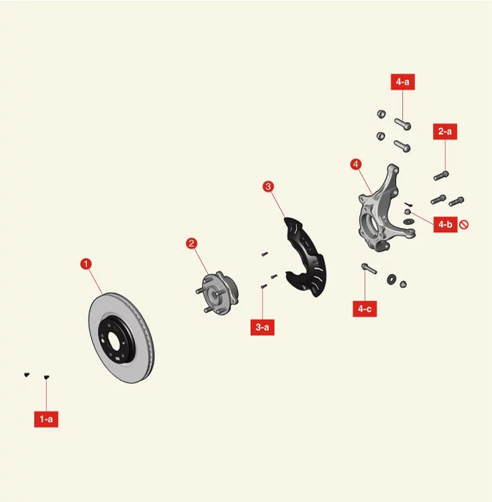
Driveshaft and Axle — Front Axle Assembly / Components and Components Location / Component illustration

1. Front Brake Disc
1-a. 4.9 - 5.9 N·m (0.5 - 0.6 kgf·m, 3.6 - 4.3 lb·ft, 43.4 - 52.1 lb·in)
2. Front Hub Assembly
2-a. 78.5 - 98.1 N·m (8.0 - 10.0 kgf·m, 57.9 - 72.3 lb·ft)
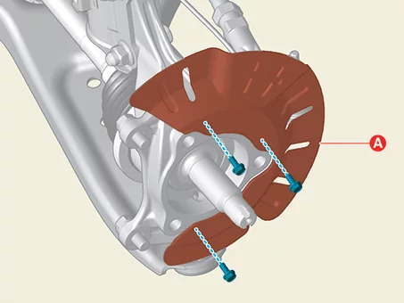
3. Front Dust Cover
3-a. 7.8 - 11.8 N·m (0.8 - 1.2 kgf·m, 5.8 - 8.7 lb·ft)
4. Front Knuckle
4-a. 137.3 - 156.9 N·m (14.0 - 16.0 kgf·m, 101.3 - 115.7 lb·ft)
4-b. 34.3 - 44.1 N·m (3.5 - 4.5 kgf·m, 25.3 - 32.5 lb·ft)
4-c. 58.8 - 70.6 N·m (6.0 - 7.2 kgf·m, 43.4 - 52.1 lb·ft)

Front Hub Assembly Removal and Installation

Special Service Tool
Tool Name / Number
Illustration
Description
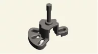
CV joint puller
09517 - 4E000

Driveshaft and Axle — Front Axle Assembly / Front Hub Assembly / Removal and Installation / Special Service Tool illustration

Used for removal of CV joint

Removal
1.
Remove the front wheel and tires.
(Refer to Suspension System - "Wheel")
2.
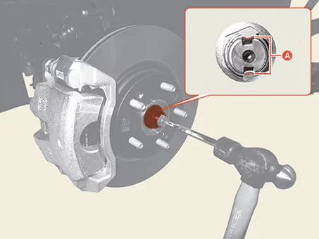
Unlock the driveshaft lock nut caulking (A), by hammering on a chisel or suitable tool.

Driveshaft and Axle — Front Axle Assembly / Front Hub Assembly / Removal and Installation / Removal illustration

3.
Remove the front brake disc.
(Refer to Brake System - "Front Brake Disc")
4.
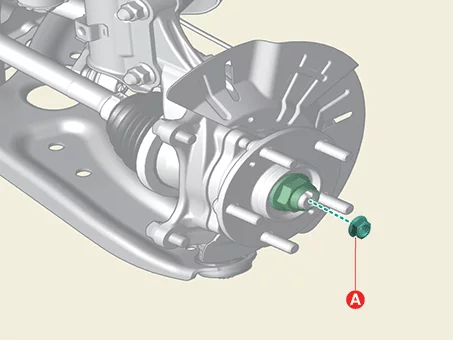
Remove the driveshaft lock nut (A).

Tightening torque :
274.6 - 294.2 N·m (28.0 - 30.0 kgf·m, 202.5 - 217 lb·ft)

Driveshaft and Axle — Front Axle Assembly / Front Hub Assembly / Removal and Installation / Removal illustration

5.
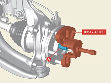
Separate the front driveshaft (A) from the front hub assembly using the SST (09517 - 4E000).

Driveshaft and Axle — Front Axle Assembly / Front Hub Assembly / Removal and Installation / Removal illustration

6.
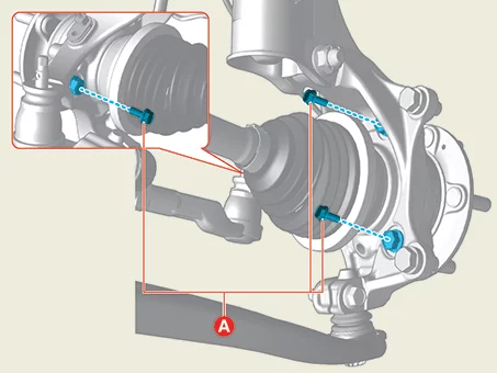
Remove the front hub assembly bolts (A).

Tightening torque :
78.5 - 98.1 N·m (8.0 - 10.0 kgf·m, 57.9 - 72.3 lb·ft)

Driveshaft and Axle — Front Axle Assembly / Front Hub Assembly / Removal and Installation / Removal illustration

7.
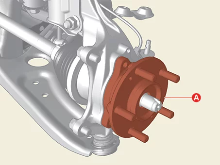
Remove the front hub assembly (A).

Driveshaft and Axle — Front Axle Assembly / Front Hub Assembly / Removal and Installation / Removal illustration

Installation
1.
Install in reverse order of removal.
Note    
•
Do not reuse the driveshaft lock nut.
•
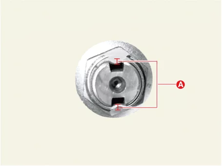
After tightening the driveshaft lock nut, caulk the lock nut to an appropriate depth (A) by using a chisel or suitable tool.

Caulking Depth (A) : 1.5 mm (0.059 in.) or more

Driveshaft and Axle — Front Axle Assembly / Front Hub Assembly / Removal and Installation / Installation illustration

•
Press the brake pedal to prevent the driveshaft from rotating when tightening the driveshaft lock nut.

Front Hub Assembly Inspection

Inspection
1.
Check the hub for cracks and spline wear.
2.
Check the hub bearing for defects.

Front Dust Cover Removal and Installation

Removal
1.
Remove the front hub assembly.
(Refer to Front Axle Assembly - "Front Hub Assembly")
2.
Remove the front dust cover (A) after removing the bolts.

Tightening torque :
7.8 - 11.8 N·m (0.8 - 1.2 kgf·m, 5.8 - 8.7 lb·ft)

Driveshaft and Axle — Front Axle Assembly / Front Dust Cover / Removal and Installation / Removal illustration

Installation
1.
Install in reverse order of removal.

Front Dust Cover Inspection

Inspection
1.
Check the front dust cover for cracks, defects.

Front Knuckle Removal and Installation

Special Service Tool
Tool Name / Number
Illustration
Description
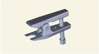
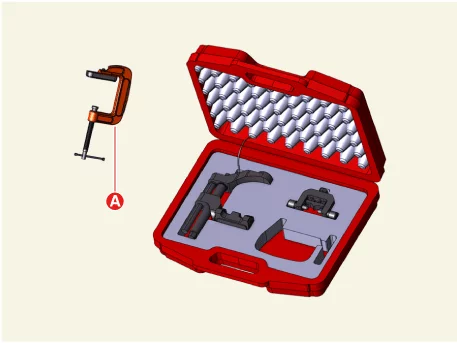
Ball joint puller
09568 - 1S100

Driveshaft and Axle — Front Axle Assembly / Front Knuckle / Removal and Installation / Special Service Tool illustration

Used for removal of the tie rod end ball joint
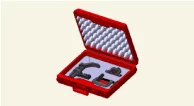
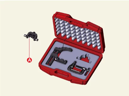
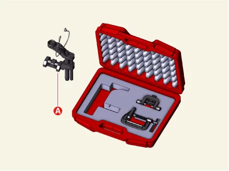
Lower arm ball joint remover
0K545 - A9100

Driveshaft and Axle — Front Axle Assembly / Front Knuckle / Removal and Installation / Special Service Tool illustration

Used for removal of front lower arm ball joint

Removal
1.
Remove the front dust cover.
(Refer to Front Axle Assembly - "Front Dust Cover")
2.
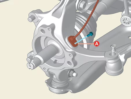
Remove the front wheel speed sensor (A) after removing the bolt.

Tightening torque :
6.9 - 10.8 N·m (0.7 - 1.1 kgf·m, 5.1 - 8 lb·ft)

Driveshaft and Axle — Front Axle Assembly / Front Knuckle / Removal and Installation / Removal illustration

3.
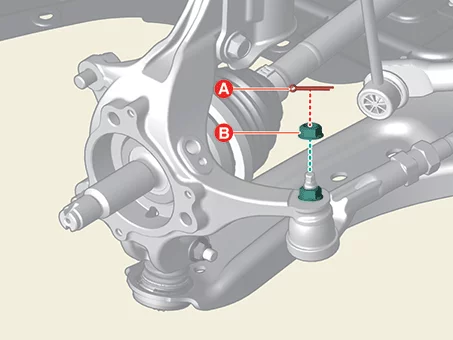
Separate the tie rod end ball joint from the front axle.
(1)
Remove the split pin (A).
(2)
Remove the lock nut (B).

Tightening torque :
34.3 - 44.1 N·m (3.5 - 4.5 kgf·m, 25.3 - 32.5 lb·ft)

Driveshaft and Axle — Front Axle Assembly / Front Knuckle / Removal and Installation / Removal illustration

Note    
•
Do not reuse the split pin.
•
Do not reuse the lock nut.
•
Be careful not to damage the boot of the link.
•
Use a hand tool when removing or installing the lock nut.
(3)
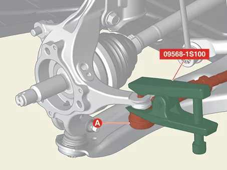
Separate the tie rod end ball joint (A) using the SST (09568 - 1S100).

Driveshaft and Axle — Front Axle Assembly / Front Knuckle / Removal and Installation / Removal illustration

Note    

Driveshaft and Axle — Front Axle Assembly / Front Knuckle / Removal and Installation / Removal illustration

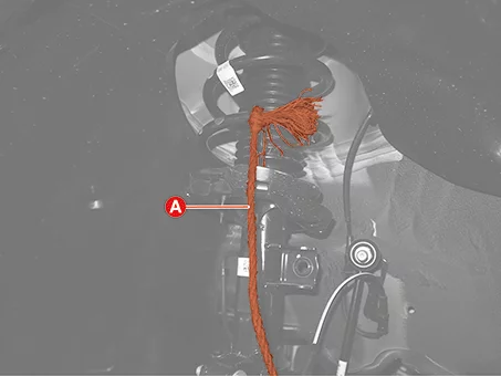
Secure the SST (09568 - 1S100) to prevent it from falling off using the wire (A).
4.
Separate the lower arm ball joint from the front axle.
(1)
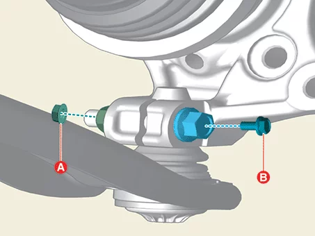
Remove the lower arm nut (A) and bolt (B).

Tightening torque :
58.8 - 70.6 N·m (6.0 - 7.2 kgf·m, 43.4 - 52.1 lb·ft)

Driveshaft and Axle — Front Axle Assembly / Front Knuckle / Removal and Installation / Removal illustration

Information    
Fix the lower arm ball joint bolt when removing or installing the nut.
Note    
•
Do not reuse the split pin.
•
Be careful not to change the bolt, nut and washer installing position.
(2)
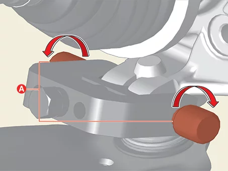
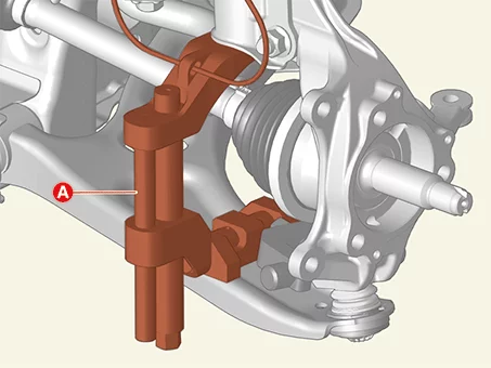
Install the support bolt to the lower arm ball joint mounting hole, and then rotate the bolts (A).

Driveshaft and Axle — Front Axle Assembly / Front Knuckle / Removal and Installation / Removal illustration

Information    
Use the support bolt (A) of the SST (0K545 - A9100).

Driveshaft and Axle — Front Axle Assembly / Front Knuckle / Removal and Installation / Removal illustration

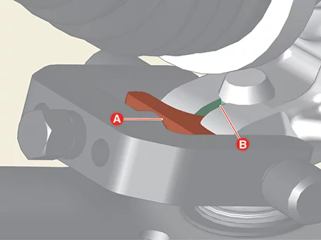
(3)
Place the support body (A) between the lower arm and the front axle (B).

Driveshaft and Axle — Front Axle Assembly / Front Knuckle / Removal and Installation / Removal illustration

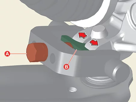
(4)
Rotate the bolt (A) clockwise, and then insert the support body (B) to broaden the gap.

Driveshaft and Axle — Front Axle Assembly / Front Knuckle / Removal and Installation / Removal illustration

(5)
Install the main body (A) between the front strut assembly and front lower arm.

Driveshaft and Axle — Front Axle Assembly / Front Knuckle / Removal and Installation / Removal illustration

Information    
Use the main body (A) of the SST (0K545 - A9100).

Driveshaft and Axle — Front Axle Assembly / Front Knuckle / Removal and Installation / Removal illustration

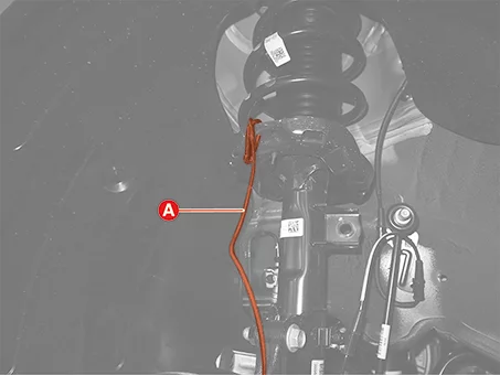
(6)
Secure the main body with the wire (A) to prevent it from falling.

Driveshaft and Axle — Front Axle Assembly / Front Knuckle / Removal and Installation / Removal illustration

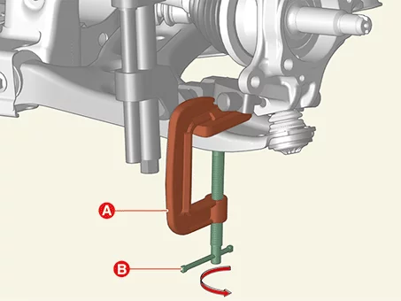
(7)
Install the C-clamp (A) by turning the handle (B) to prevent the main body from slipping.

Driveshaft and Axle — Front Axle Assembly / Front Knuckle / Removal and Installation / Removal illustration

Information    
Use the C-clamp (A) of the SST (0K545 - A9100).

Driveshaft and Axle — Front Axle Assembly / Front Knuckle / Removal and Installation / Removal illustration

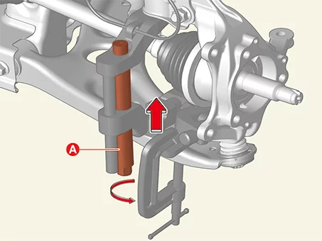
(8)
Tighten the bolt (A), and then separate the front lower arm from the front axle.

Driveshaft and Axle — Front Axle Assembly / Front Knuckle / Removal and Installation / Removal illustration

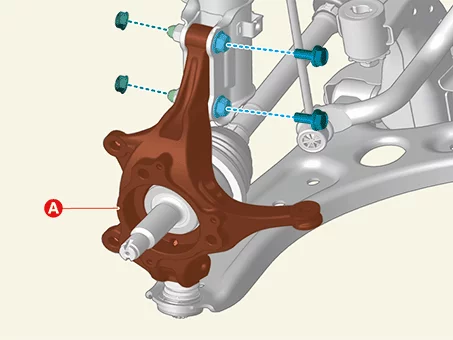
5.
Remove the front knuckle (A) after removing the bolts and nuts.

Tightening torque :
137.3 - 156.9 N·m (14.0 - 16.0 kgf·m, 101.3 - 115.7 lb·ft)

Driveshaft and Axle — Front Axle Assembly / Front Knuckle / Removal and Installation / Removal illustration

Installation
1.
Install in reverse order of removal.
2.
Check the alignment.
(Refer to Suspension System - "Alignment")

Front Knuckle Inspection

Inspection
1.
Check the front knuckle for cracks.

Other information:

Kia Seltos SP2 (2021-2026) Service Manual: Electronic Parking Brake (EPB) Description and Operation

Description The Electric Parking Brake (EPB) is a parking brake system that operates the actuators of each caliper using an electrical signal via button operation, unlike a parking brake operated by a lever or pedal. The EPB has the function to engage the parking brake when the vehicle is stationary, to assist in braking in emergencies due to brake failure, and to engage the parking brake automatically when the engine off.

Kia Seltos SP2 (2021-2026) Service Manual: Rear Cross-Traffic Collision-Avoidance Assist (RCCA)

Rear Cross-Traffic Collision-Avoidance Assist (RCCA) in the Kia Seltos is designed to help detect vehicles approaching from the rear left or rear right side while the vehicle is reversing. If a collision risk is detected, the system may warn the driver with a warning message and an audible alert. Braking assist may also be applied depending on the situation.