
Kia Seltos SP2 (2021-2026) Service Manual / Body Electrical System / Power Windows
Kia Seltos: Body Electrical System / Power Windows
Contents:
- On Vehicle Inspection
- Power Window Motor Terminal Function
- Power Window Motor Removal and Installation
- Power Window Switch Terminal Function
- Power Window Switch Removal and Installation
On Vehicle Inspection
| On Vehicle Inspection |
| Diagnosis with KDS |
| 1. |
The power windows can be more quickly diagnosed for problems with the KDS (Refer to "DTC guide").
|
Power Window Motor Terminal Function
| Connector and Terminal Function |
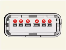
| [Safety Window Motor] |
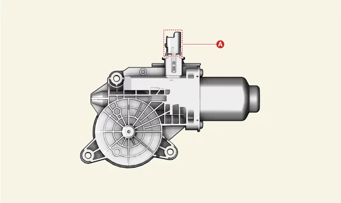
|
Connector A |
Terminal |
Function |
|
|
1 |
Switch signal |
|
2 |
- |
|
|
3 |
Ground |
|
|
4 |
Battery (+) |
|
|
5 |
- |
|
|
6 |
LIN |
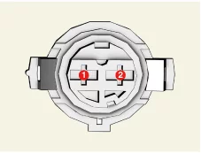
| [Manual Window Motor] |
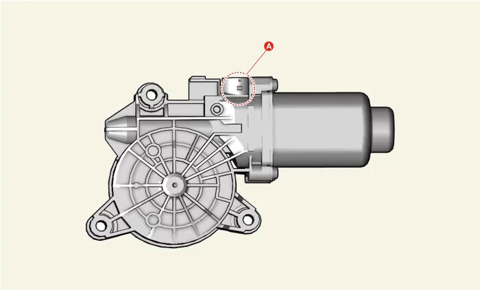
| Connector A |
Position |
Operate |
Terminal |
|
|
1 |
2 |
|||
|
|
LH |
Up (Counterclockwise) |
+ |
- |
|
Down (Clockwise) |
- |
+ |
||
| RH |
Up (Clockwise) |
+ |
- |
|
|
Down (Counterclockwise) |
- |
+ |
||
Power Window Motor Removal and Installation
| Removal |
Front Power Window Motor
| 1. |
Remove the front door trim.
(Refer to Body - "Front Door Trim")
|
| 2. |
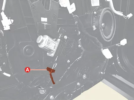
Disconnect the front power window motor connector (A).
|
| 3. |
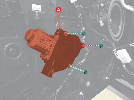
Remove the front power window motor (A) after removing the bolts.
|
Rear Power Window Motor
| 1. |
Remove the rear door trim.
(Refer to Body - "Rear Door Trim")
|
| 2. |
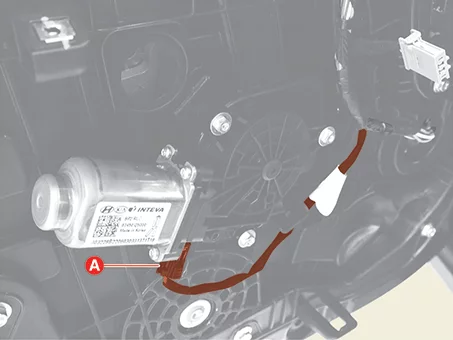
Disconnect the rear power window motor connector (A).
|
| 3. |
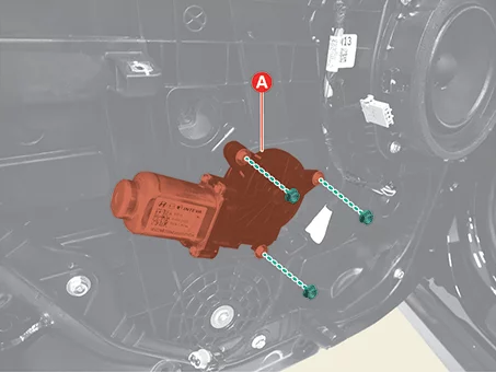
Remove the rear power window motor (A) after removing the bolts.
|
| Installation |
| 1. |
Install in reverse order of removal.
|
Power Window Switch Terminal Function
| Connector and Terminal Function |
Power Window Main Switch
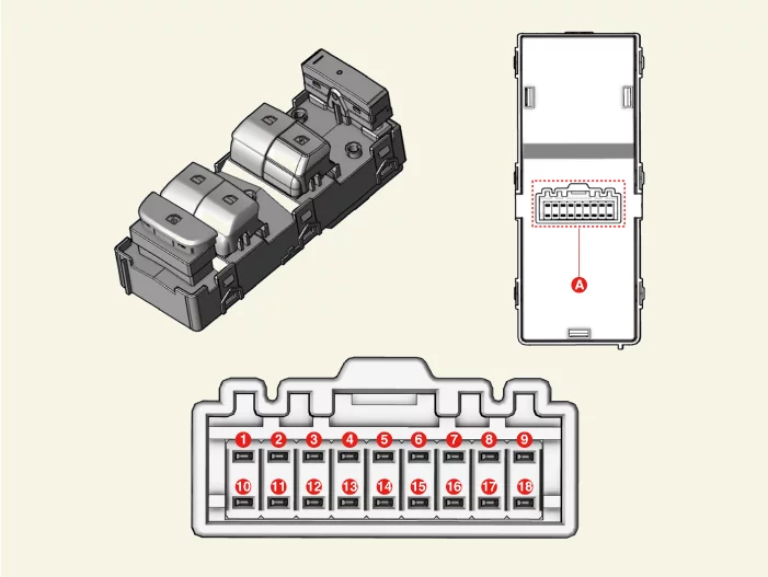
[Safety Power Window]
| Terminal |
Connector A |
||
|
Function |
Terminal |
Function |
|
|
1 |
Battery (+) |
10 |
Right rear power window switch (Lock) |
|
2 |
Passenger seat power window switch (Up) |
11 |
Right rear power window switch (Down) |
|
3 |
Passenger seat power window switch (Down) |
12 |
Right rear power window switch (Up) |
|
4 |
Illumination ( + ) |
13 |
Left rear power window switch (Lock) |
|
5 |
Door lock switch |
14 |
Left rear power window switch (Up) |
|
6 |
Door unlock switch |
15 |
- |
|
7 |
Ground |
16 |
- |
|
8 |
Door unlock IND |
17 |
Left rear power window switch (Down) |
|
9 |
Driver seat safety power window module |
18 |
Ground |
[Auto-down Power Window]
| Terminal |
Connector A |
||
|
Function |
Terminal |
Function |
|
|
1 |
Battery (+) |
10 |
Right rear power window switch (Lock) |
|
2 |
Passenger seat power window switch (Up) |
11 |
Right rear power window switch (Down) |
|
3 |
Passenger seat power window switch (Down) |
12 |
Right rear power window switch (Up) |
|
4 |
Illumination ( + ) |
13 |
Left rear power window switch (Lock) |
|
5 |
Door lock switch |
14 |
Left rear power window switch (Up) |
|
6 |
Door unlock switch |
15 |
Battery ( + )_LH |
|
7 |
Driver seat power window motor (Down) |
16 |
- |
|
8 |
Door unlock IND |
17 |
Left rear power window switch (Down) |
|
9 |
Driver seat power window motor (Up) |
18 |
Ground |
Power Window Sub Switch
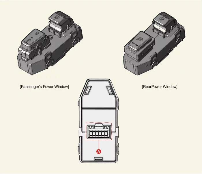
[Passenger Seat Power Window]
|
Connector A |
Terminal |
Function |
Terminal |
Function |
|
|
1 |
Battery (+)_RH |
7 |
Passenger seat power window switch (Down) |
|
2 |
Door unlock switch |
8 |
Ground |
|
|
3 |
Passenger seat power window motor (Up) |
9 |
- |
|
|
4 |
Door lock switch |
10 |
Passenger seat power window switch (Up) |
|
|
5 |
Passenger seat power window motor (Down) |
11 |
Illumination ( + ) |
|
|
6 |
Door unlock IND |
12 |
Battery (+) |
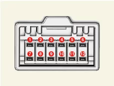
[Rear Power Window]
|
Connector A |
Terminal |
Function |
Terminal |
Function |
|
|
1 |
Battery (+) |
7 |
Rear power window switch (Down) |
|
2 |
Rear seat heater IND (High) |
8 |
Ground |
|
|
3 |
Rear power window motor (Up) |
9 |
- |
|
|
4 |
Rear seat heater IND (Low) |
10 |
Rear power window switch (Up) |
|
|
5 |
Rear power window motor (Down) |
11 |
Illumination ( + ) |
|
|
6 |
Rear seat heater switch signal |
12 |
Rear power window switch (Lock) |
Power Window Switch Removal and Installation
| Removal |
Power Window Main Switch
| 1. |
Remove the front door trim [Driver's Side].
(Refer to Body - "Front Door Trim")
|
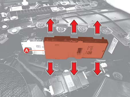
| 2. |
Remove the power window main switch (A) after pulling the hooks in the direction of arrow.
|
Power Window Sub Switch
| 1. |
Remove the front door trim [Passenger's Side].
(Refer to Body - "Front Door Trim")
|
| 2. |
Remove the power window sub switch (A) after pulling the hooks in the direction of arrow.
|
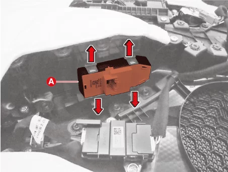
Power Window Rear Switch
| 1. |
Remove the rear door trim.
(Refer to Body - "Rear Door Trim")
|
| 2. |
Remove the power window rear switch (A) after pulling the hooks in the direction of arrow.
|
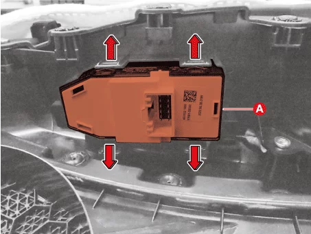
| Installation |
| 1. |
Install in reverse order of removal.
|


Other information:
Kia Seltos SP2 (2021-2026) Service Manual: LCD display
The Kia Seltos LCD display modes can be changed using the control buttons on the steering wheel. These modes provide access to driving information, vehicle settings, warning messages, and system status screens. LCD Display Control : MODE button for changing display modes / : MOVE switch for changing items OK: SELECT/RESET button for selecting, confirming, or resetting the highlighted itemKia Seltos SP2 (2021-2026) Service Manual: Manual Speed Limit Assist (MSLA)
Speed Limit indicator Set speed Manual Speed Limit Assist allows the Kia Seltos driver to set a speed limit when they do not want the vehicle to exceed a specific speed. If the vehicle speed goes above the preset limit, MSLA will operate. The set speed limit will blink and a warning chime will sound until the Kia Seltos returns to a speed within the selected limit.