
Kia Seltos: Suspension System / Rear Suspension System - Multi Link
Contents:
- Components and Components Location
- Rear Shock Absorber Components and Components Location
- Rear Shock Absorber Removal and Installation
- Rear Shock Absorber Disassembly
- Rear Shock Absorber Inspection
- Rear Shock Absorber Reassembly
- Rear Coil Spring Components and Components Location
- Rear Coil Spring Removal and Installation
- Rear Coil Spring Inspection
- Rear Upper Arm Components and Components Location
- Rear Upper Arm Removal and Installation
- Rear Upper Arm Inspection
- Rear Lower Arm Components and Components Location
- Rear Lower Arm Removal and Installation
- Rear Lower Arm Inspection
- Rear Assist Arm Components and Components Location
- Rear Assist Arm Removal and Installation
- Rear Assist Arm Inspection
- Trailing Arm Components and Components Location
- Trailing Arm Removal and Installation
- Trailing Arm Inspection
- Rear Stabilizer Bar Components and Components Location
- Rear Stabilizer Bar Removal and Installation
- Rear Stabilizer Bar Inspection
- Rear Cross Member Components and Components Location
- Rear Cross Member Removal and Installation
- Rear Cross Member Inspection
Components and Components Location
| Component |
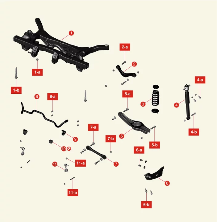
| 1. Rear Cross Member 1-a. 156.9 - 176.5 N·m (16.0 - 18.0 kgf·m, 115.7 - 130.2 lb·ft) 1-b. 156.9 - 176.5 N·m (16.0 - 18.0 kgf·m, 115.7 - 130.2 lb·ft) 2. Rear Upper Arm 2-a. 137.3 - 156.9 N·m (14.0 - 16.0 kgf·m, 101.3 - 115.7 lb·ft) 3. Coil Spring 4. Rear Shock Absorber 4-a. 58.8 - 73.5 N·m (6.0 - 7.5 kgf·m, 43.4 - 54.2 lb·ft) 4-b. 98.1 - 117.7 N·m (10.0 - 12.0 kgf·m, 72.3 - 86.8 lb·ft) 5. Rear Lower Arm 5-a. 107.9 - 117.7 N·m (11.0 - 12.0 kgf·m, 79.6 - 86.8 lb·ft) 5-b. 137.3 - 156.9 N·m (14.0 - 16.0 kgf·m, 101.3 - 115.7 lb·ft) |
6. Trailing Arm 6-a. 137.3 - 156.9 N·m (14.0 - 16.0 kgf·m, 101.3 - 115.7 lb·ft) 6-b. 98.1 - 117.7 N·m (10.0 - 12.0 kgf·m, 72.3 - 86.8 lb·ft) 7. Rear Assist Arm 7-a. 107.9 - 117.7 N·m (11.0 - 12.0 kgf·m, 79.6 - 86.8 lb·ft) 7-b. 137.3 - 156.9 N·m (14.0 - 16.0 kgf·m, 101.3 - 115.7 lb·ft) 8. Rear Stabilizer Bar 8-a. 44.1 - 53.9 N·m (4.5 - 5.5 kgf·m, 32.5 - 39.8 lb·ft) 9. Rear Stabilizer Bar Bracket 10. Rear Stabilizer Bar Bushing 11. Rear Stabilizer Bar Link 11-a. 58.8 - 78.5 N·m (6.0 - 8.0 kgf·m, 43.4 - 57.9 lb·ft) 11-b. 19.6 - 29.4 N·m (2.0 - 3.0 kgf·m, 14.5 - 21.7 lb·ft) |
Rear Shock Absorber Components and Components Location
| Component and Component Location |
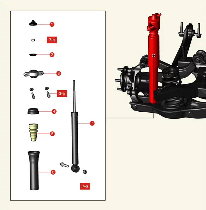
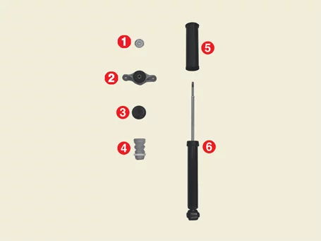
| 1. Insulator Cap 2. Retainer 3. Insulator 3-a. 49.0 - 63.7 N·m (5.0 - 6.5 kgf·m, 36.2 - 47 lb·ft) |
4. Retainer Cup 5. Bumper Rubber 6. Dust Cover 7. Shock Absorber Assembly 7-a. 21.6 - 29.4 N·m (2.2 - 3.0 kgf·m, 15.9 - 21.7 lb·ft) 7-b. 98.1 - 117.7 N·m (10.0 - 12.0 kgf·m, 72.3 - 86.8 lb·ft) |
Rear Shock Absorber Removal and Installation
| Removal |
| 1. |
Remove the rear wheel and tires.
(Refer to Tires/Wheels - "Wheel")
|
| 2. |
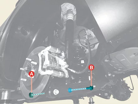
Remove the rear shock absorber lower nut (A) and bolt (B).
|


| 3. |
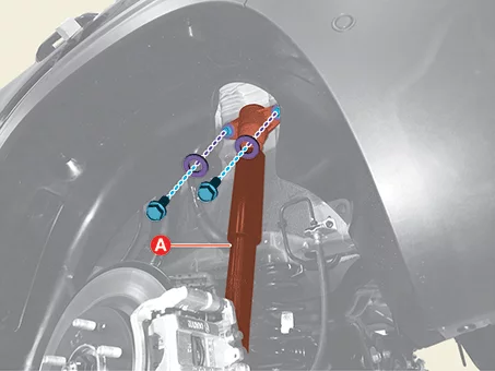
Remove the rear shock absorber (A) after removing the bolts and washers.
|
| Installation |
| 1. |
Install in reverse order of removal.
|
Rear Shock Absorber Disassembly
| Special Service Tool |
|
Tool Name / Number |
Illustration |
Description |
|
Shock absorber lock nut remover. 09546 - 3X100 |
|
Used for removal or installing of rear shock absorber lock nut. |
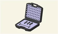
| Disassembly |
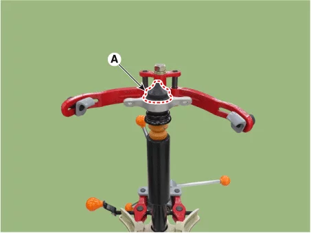
| 1. |
Remove the insulator cap (A).
|
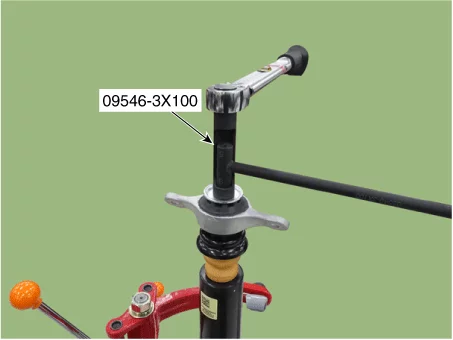
| 2. |
Remove the self locking nut using the SST (09546 - 3X100).
|
| 3. |
Disassemble the rear shock absorber.
|
Rear Shock Absorber Inspection
| Inspection |
| 1. |
Check the rubber parts for damage or deterioration.
|
| 2. |
Check all bolts and nuts.
|
| 3. |
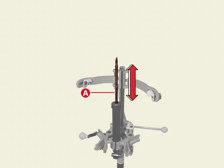
Repeat compression and tension of the rear shock absorber rod (A) to check for abnormal resistance or
noise between operations.
|
| Disposal |
| 1. |
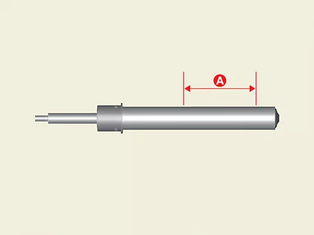
Fully extend the piston rod.
|
| 2. |
Drill a hole on the A section to remove gas from the cylinder.
|
Rear Shock Absorber Reassembly
| Special Service Tool |
|
Tool Name / Number |
Illustration |
Description |
|
Shock absorber lock nut remover. 09546 - 3X100 |
|
Used for removal or installing of rear shock absorber lock nut. |
| Reassembly |
| 1. |
Reassemble the rear shock absorber assembly.
|
| 2. |
Install the self locking nut using the SST (09546 - 3X100).
|
| 3. |
Remove the insulator cap (A).
|
Rear Coil Spring Components and Components Location
| Component and Component Location |
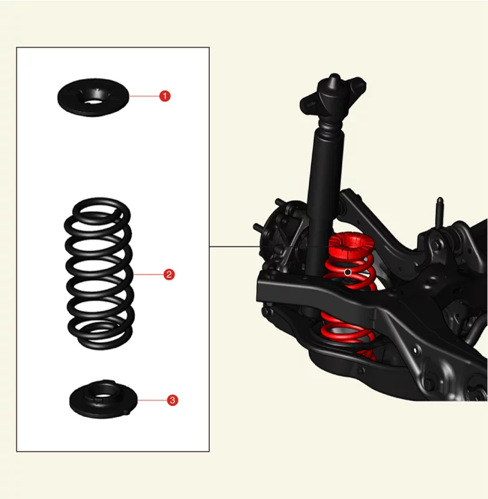
| 1. Coil Spring Upper Pad 2. Coil Spring 3. Coil Spring Lower Pad |
Rear Coil Spring Removal and Installation
| Removal |
If a transmission jack is used with a two-post lift, do not lift the vehicle too much. The center gravity
of the vehicle may change and fall.
|
| 1. |
Remove the rear wheel and tires.
(Refer to Tires/Wheels - "Wheel")
|
| 2. |
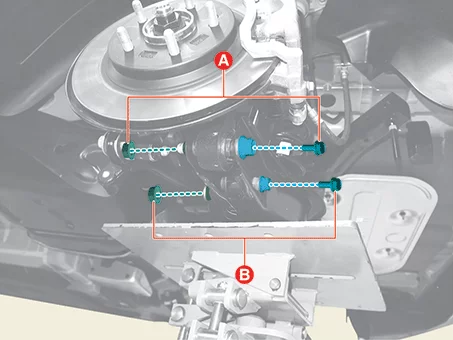
Remove the rear lower arm bolts and nuts (A, B).
|
| 3. |
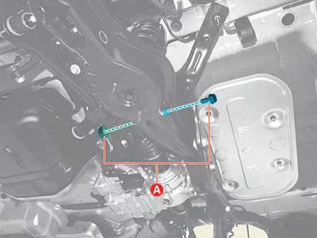
Remove the rear stabilizer bar link nut and bolt (A).
|
| 4. |
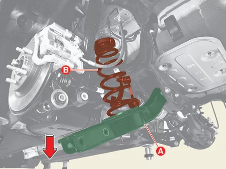
Down the rear lower arm (A), and then remove the rear coil spring (B).
|
| 5. |
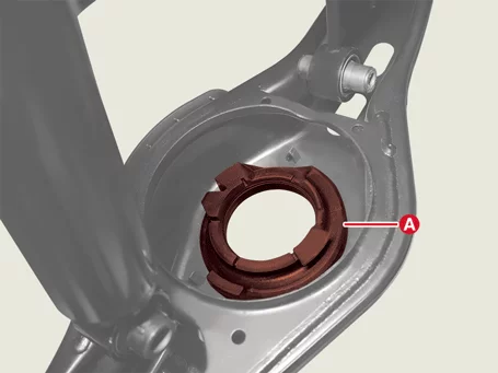
Remove the rear coil spring lower pad (A) from the rear lower arm.
|
| Installation |
| 1. |
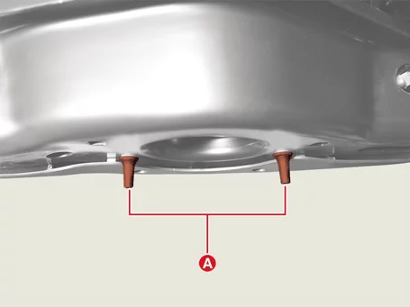
Install in reverse order of removal.
|
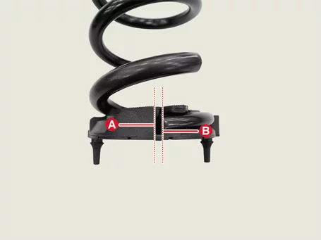
| 2. |
Check the alignment.
(Refer to Alignment - "Repair Procedures")
|
Rear Coil Spring Inspection
| Inspection |
| 1. |
Check the coil spring for cracks or deformation.
|
| 2. |
Check the coil spring pad for damage and deformation.
|
Rear Upper Arm Components and Components Location
| Component and Component Location |
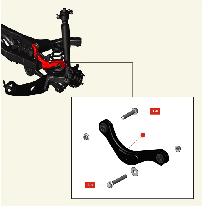
| 1. Rear Upper Arm 1-a. 137.3 - 156.9 N·m (14.0 - 16.0 kgf·m, 101.3 - 115.7 lb·ft) 1-b. 137.3 - 156.9 N·m (14.0 - 16.0 kgf·m, 101.3 - 115.7 lb·ft) |
Rear Upper Arm Removal and Installation
| Removal |
If a transmission jack is used with a two-post lift, do not lift the vehicle too much. The center gravity
of the vehicle may change and fall.
|
| 1. |
Remove the rear wheel and tires.
(Refer to Tires/Wheels - "Wheel")
|
| 2. |
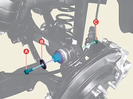
Remove the rear upper arm bolt (A), washer (B), and nut (C).
|
| 3. |
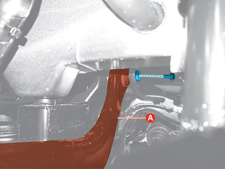
Remove the rear upper arm (A) after removing the bolt.
|
| Installation |
| 1. |
Install in reverse order of removal.
|
| 2. |
Check the alignment.
(Refer to Alignment - "Repair Procedures")
|
Rear Upper Arm Inspection
| Inspection |
| 1. |
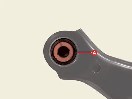
Check the bushing (A) for wear and aging.
|
| 2. |
Check the rear upper arm for bent or damage.
|
| 3. |
Check all bolts and nuts.
|
Rear Lower Arm Components and Components Location
| Component and Component Location |
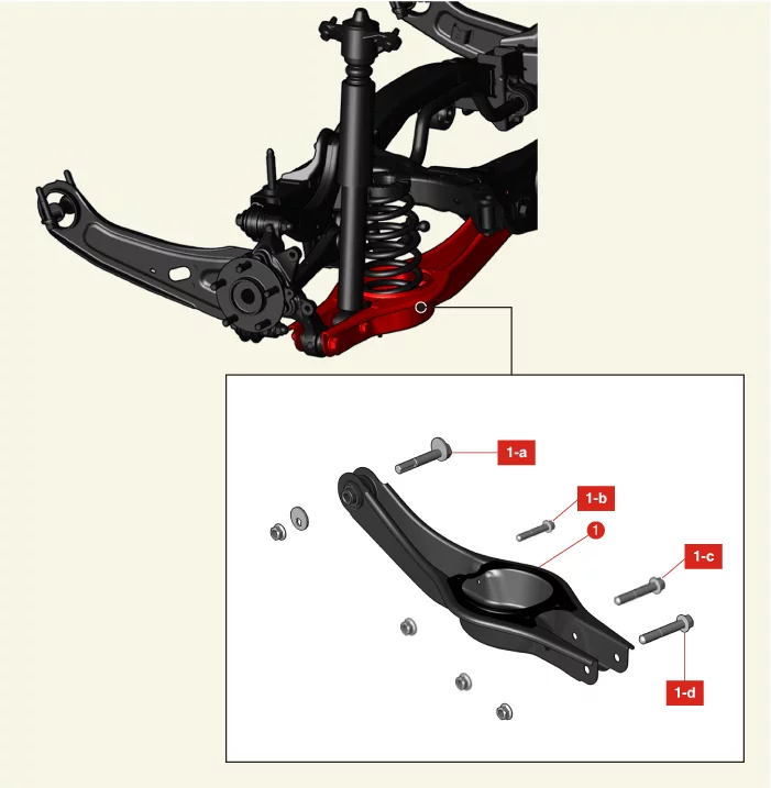
| 1. Rear Lower Arm 1-a. 107.9 - 117.7 N·m (11.0 - 12.0 kgf·m, 79.6 - 86.8 lb·ft) 1-b. 19.6 - 29.4 N·m (2.0 - 3.0 kgf·m, 14.5 - 21.7 lb·ft) 1-c. 98.1 - 117.7 N·m (10.0 - 12.0 kgf·m, 72.3 - 86.8 lb·ft) 1-d. 137.3 - 156.9 N·m (14.0 - 16.0 kgf·m, 101.3 - 115.7 lb·ft) |
Rear Lower Arm Removal and Installation
| Removal |
| 1. |
Remove the rear coil spring.
(Refer to Rear Suspension System - "Rear Coil Spring")
|
| 2. |
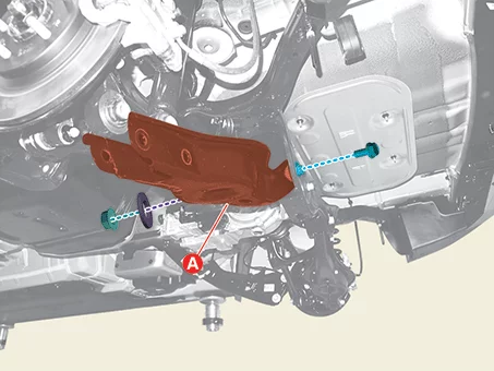
Remove the rear lower arm (A) after removing the bolt, nut, and plate.
|
| Installation |
| 1. |
Install in reverse order of removal.
|
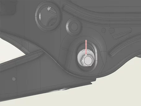
| 2. |
Check the alignment.
(Refer to Alignment - "Repair Procedures")
|
Rear Lower Arm Inspection
| Inspection |
| 1. |
Check the bushing for wear and aging.
|
| 2. |
Check the rear lower arm for bent or damage.
|
| 3. |
Check all bolts and nuts.
|
Rear Assist Arm Components and Components Location
| Component and Component Location |
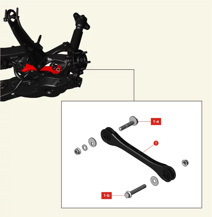
| 1. Rear Assist Arm 1-a. 107.9 - 117.7 N·m (11.0 - 12.0 kgf·m, 79.6 - 86.8 lb·ft) 1-b. 137.3 - 156.9 N·m (14.0 - 16.0 kgf·m, 101.3 - 115.7 lb·ft) |
Rear Assist Arm Removal and Installation
| Removal |
If a transmission jack is used with a two-post lift, do not lift the vehicle too much. The center gravity
of the vehicle may change and fall.
|
| 1. |
Remove the rear wheel and tires.
(Refer to Tires/Wheels - "Wheel")
|
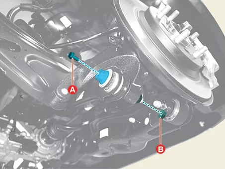
| 2. |
Remove the rear assist arm bolt (A) and nut (B).
|
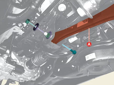
| 3. |
Remove the rear assist arm (A) after removing the bolt, nut, and plate.
|
| Installation |
| 1. |
Install in reverse order of removal.
|
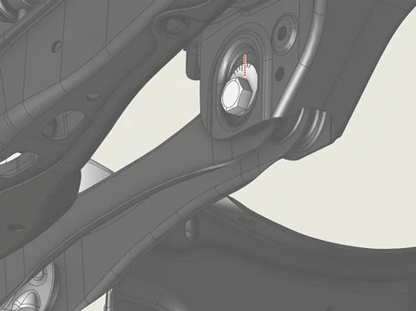
| 2. |
Check the alignment.
(Refer to Alignment - "Repair Procedures")
|
Rear Assist Arm Inspection
| Inspection |
| 1. |
Check the bushing (A) for wear and aging.
|
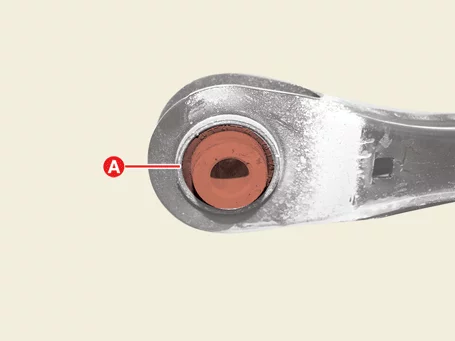
| 2. |
Check the rear assist arm for bent or damage.
|
| 3. |
Check all bolts.
|
Trailing Arm Components and Components Location
| Component and Component Location |
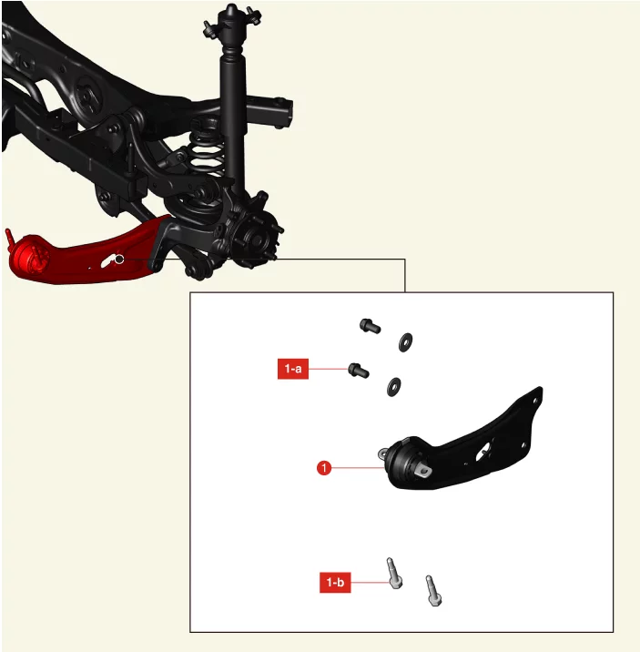
| 1. Trailing Arm 1-a. 137.3 - 156.9 N·m (14.0 - 16.0 kgf·m, 101.3 - 115.7 lb·ft) 1-b. 98.1 - 117.7 N·m (10.0 - 12.0 kgf·m, 72.3 - 86.8 lb·ft) |
Trailing Arm Removal and Installation
| Removal |
| 1. |
Remove the rear wheel and tires.
(Refer to Tires/Wheels - "Wheel")
|
| 2. |
Remove the trailing arm bolts (A), washers (B), and EPB wire bracket nut (C).
|
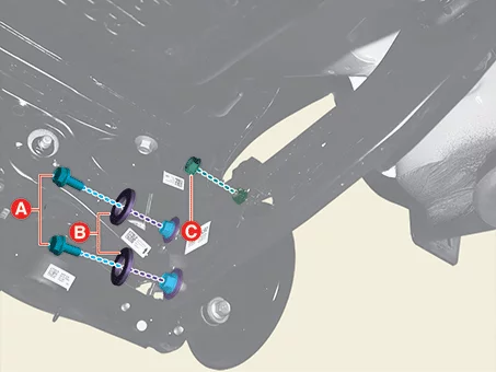
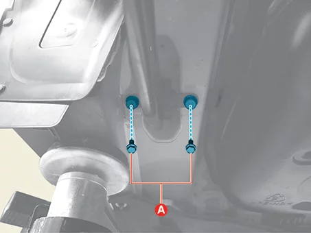
| 3. |
Remove the trailing arm after removing the bolts (A).
|
| Installation |
| 1. |
Install in reverse order of removal.
|
| 2. |
Check the alignment.
(Refer to Alignment - "Repair Procedures")
|
Trailing Arm Inspection
| Inspection |
| 1. |
Check the bushing for wear and aging.
|
| 2. |
Check the trailing arm for bent or damage.
|
| 3. |
Check all bolts and nuts.
|
Rear Stabilizer Bar Components and Components Location
| Component and Component Location |
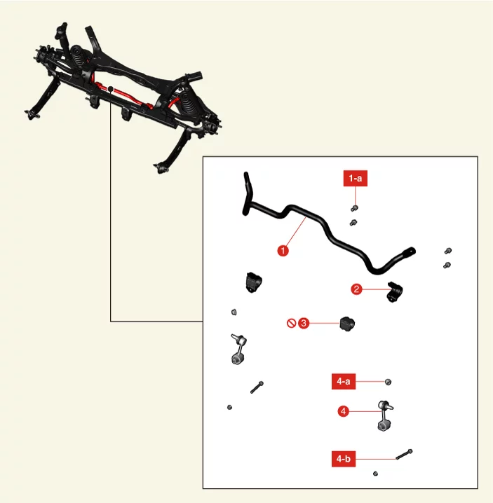
| 1. Rear Stabilizer Bar 1-a. 44.1 - 53.9 N·m (4.5 - 5.5 kgf·m, 32.5 - 39.8 lb·ft) 2. Rear Stabilizer Bar Bracket 3. Rear Stabilizer Bar Bushing |
4. Rear Stabilizer Bar Link 4-a. 58.8 - 78.5 N·m (6.0 - 8.0 kgf·m, 43.4 - 57.9 lb·ft) 4-b. 19.6 - 29.4 N·m (2.0 - 3.0 kgf·m, 14.5 - 21.7 lb·ft) |
Rear Stabilizer Bar Removal and Installation
| Removal |
| 1. |
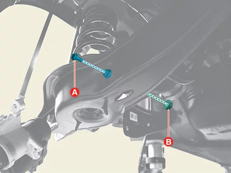
Remove the rear stabilizer bar link nuts (A) and bolts (B).
|
| 2. |
Remove the rear stabilizer bar link (A) after removing the nut.
|
| 1. |
Remove the rear differential carrier assembly.
(Refer to All Wheel Drive (AWD) System - "Differential Carrier
Assembly")
|
| 2. |
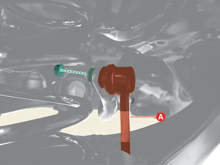
Separate the rear stabilizer bar link (A) after removing the nut.
|
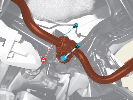
| 3. |
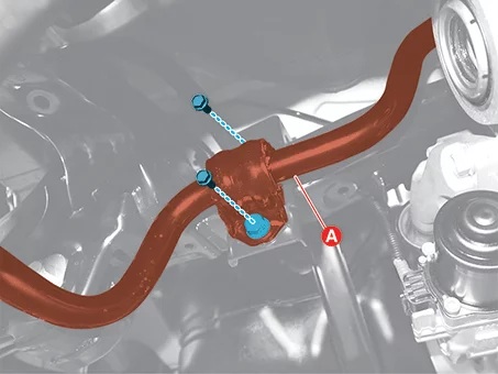
Remove the stabilizer bar (A) after removing the bolts.
[LH]
[RH]
|
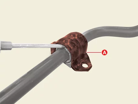
| 4. |
Remove the stabilizer bar bracket (A) using a flat-head screw driver.
|
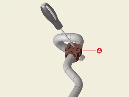
| 5. |
Remove the stabilizer bar bushing (A) using a flat-head screw driver.
|
| Installation |
| 1. |
Install in reverse order of removal.
|
| 2. |
Check the alignment.
(Refer to Alignment - "Repair Procedures")
|
Rear Stabilizer Bar Inspection
| Inspection |
| 1. |
Check the rear stabilizer bar bushing for damage.
|
| 2. |
Check the rear stabilizer bar link ball joint for damage.
|
| 3. |
Check all bolts and nuts.
|
Rear Cross Member Components and Components Location
| Component and Component Location |
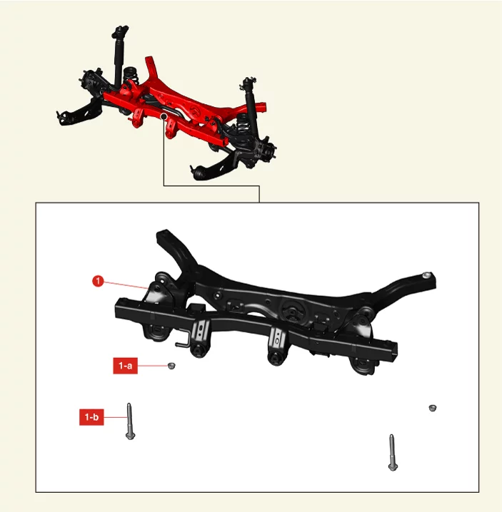
| 1. Rear Cross Member 1-a. 176.5 - 196.1 N·m (18.0 - 20.0 kgf·m, 130.2 - 144.7 lb·ft) 1-b. 176.5 - 196.1 N·m (18.0 - 20.0 kgf·m, 130.2 - 144.7 lb·ft) |
Rear Cross Member Removal and Installation
| Removal |
If a transmission jack is used with a two-post lift, do not lift the vehicle too much. The center gravity
of the vehicle may change and fall.
|
| 1. |
Remove the rear differential carrier assembly.
(Refer to All Wheel Drive (AWD) System - "Differential Carrier
Assembly")
|
| 2. |
Separate the rear shock absorbers (A) after removing the bolts and washers.
|
| 3. |
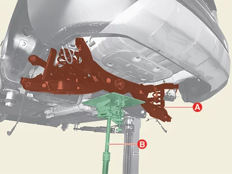
Support the rear cross member (A) with a suitable tool such as the transmission jack (B).
|
| 4. |
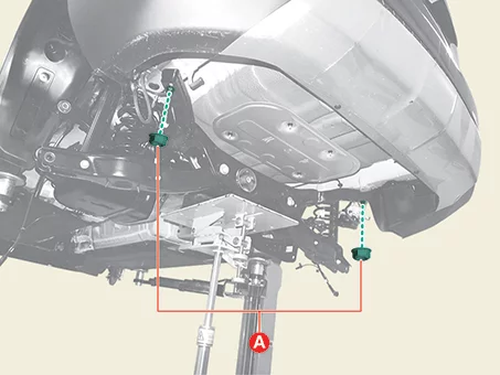
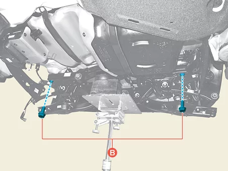
Remove the nuts (A) and bolts (B), and then lower the jack to remove the rear cross member.
|
| 5. |
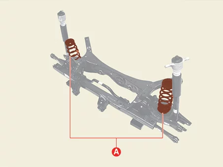
Remove the rear coil spring (A).
|
| 6. |
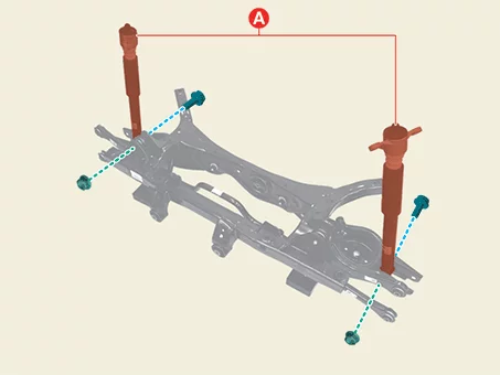
Remove the rear shock absorbers (A) after removing the bolts and nuts.
|
| 7. |
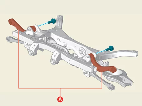
Remove the rear upper arm (A) after removing the bolt.
|
| 8. |
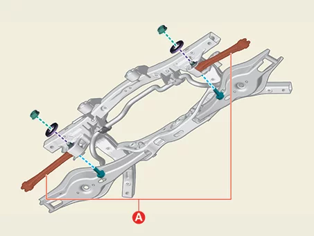
Remove the rear assist arm (A) after removing the bolt, nut, and plate.
|
| 9. |
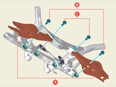
Remove the rear lower arm (A) after removing the bolt, nut, and plate.
|
| 10. |
Remove the stabilizer bar (A) after removing the bolts.
|
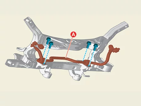
| Installation |
| 1. |
Install in reverse order of removal.
|
| 2. |
Check the alignment.
(Refer to Alignment - "Repair Procedures")
|
Rear Cross Member Inspection
| Inspection |
| 1. |
Check the bushing for aging or wearing.
|
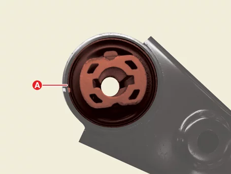
| 2. |
Check all bolts and nuts.
|


Other information:
Kia Seltos SP2 (2021-2026) Service Manual: Tire sidewall labeling
Tire sidewall information identifies and describes the basic characteristics of the tire. It also provides the Tire Identification Number (TIN), which is used for safety standard certification and may help identify a tire in case of a recall. The TIN can be used to identify the tire if a safety recall or service campaign applies.Troubleshooting • Be careful not to short-circuit the wiring by the vehicle body or other wiring.